CHAPTER 9 - WWII JAPANESE OPTICAL EQUIPMENT AND ARTILLERY SIGHTS

SECTION X - WWII JAPANESE MILITARY EQUIPMENT
SECTION I - WWII JAPANESE MILITARY EQUIPMENT INTRODUCTION.
1. GENERAL.
a. General. Most Japanese equipment shows evidence of careful thought to adapt it to the needs of the soldier. The Japanese army expects to fight, mostly on foot, in all the varied climates and terrains of Asia, where roads often are lacking. The equipment therefre is made as light in weight as is practicable, and when possible, is arranged to pack on horses or to be carried by men.
The Japanese have have given much attention to animal pack, and there are a great variety of pack saddles for specialized purposes. All of the organic heavy infantry weapons are designed for animal pack and can be manhandled when necessary.
b. The two wheeled military cart is the most common vehicle. This art, of which four types are known, is built almost entirely of wood. The smallest has a capacity of about 400 pounds. It is strong and light and is pulled by one horse which the driver leads. A larger type, of greater capacity, is pulled by two horses. A heavier miltary vehicle also has been developed which often is designed to carry artillery spare parts or other heavy equipment. This vehicle is pulled by either 2 or 4 horses.
c. Most of the Japanese Army's automotive equipment is of foreign design and construction. However, Japanese models have been designed and constructed. These are two general types: a 4 wheeled commercial design of about 2 tons capacity, and a 6-wheeled military vehicle of larger size, made in several capacities but according to the same general design. Originally, these heavier vehicles were equipped with 6 cyulinder, heavy duty, gasoline engines, but later types have Diesel engines. This trend toward Diesel power no doubt will be intensified.
d. Japanese engineering equipment is fairly complete, and includes a wide variety of amphibious, construction, maintenance, and demolition equipment. Heavier equipment, however, does not appear to have been developed on a scale comparable with the American standard. The following types of Japanese equipment are described in the chapters indicated below:
| TYPE OF EQUIPMENT | CHAPTER | |
| Air corps equipment | --------- | 4 |
| Chemical equipment | --------- | 9 |
| Armored unit equipment | --------- | 9 |
| Personal equipment | --------- | 11 |
Definite information concerning ordnance and other mobile maintenance equipment has been omitted because of lack of available data (1944). There is sufficient evidence, however, to conclude that such equipment exists in the Japanese Army.
SECTION II - WWII JAPANESE INFANTRY EQUIPMENT.
1. GENERAL.
Details of infantry equipment have not been shown in this section when it has been possible to place them under specific heading. For example, personal items issued to the individual soldier have been described, where possible, under Chapter 11, while weapons are treated in Chapter 9.
2. WWII JAPANESE OBSERVATION EQUIPMENT.
All reported specimens of Japanese optical instruments have been of good quality and have been found to resemble German designs. A particularly wide range of patterns has been developed, and specimens examined have been characterized by sturdy construction. In all cases definitions in the central part of the field of view wa good. There are no indications taht the Japanese have attempted to tropic-proof these instruments.
a. Binoculars. Details of binoculars, having a magnification in excess of 8 X, are shown in the Artillery Equipment section of this chapter. Tabulated below are the characteristics of some Japanese binoculars, of 8 X magnification or less.
| MAGNIFICATION | FIELD OF VIEW | SIZE OF OBJECTIVE LENS |
| 8 X | 6.25 degrees | 56-mm |
| 7 X | 7.1 degrees | 50-mm |
| 6 X | 9.3 degrees | 24-mm |
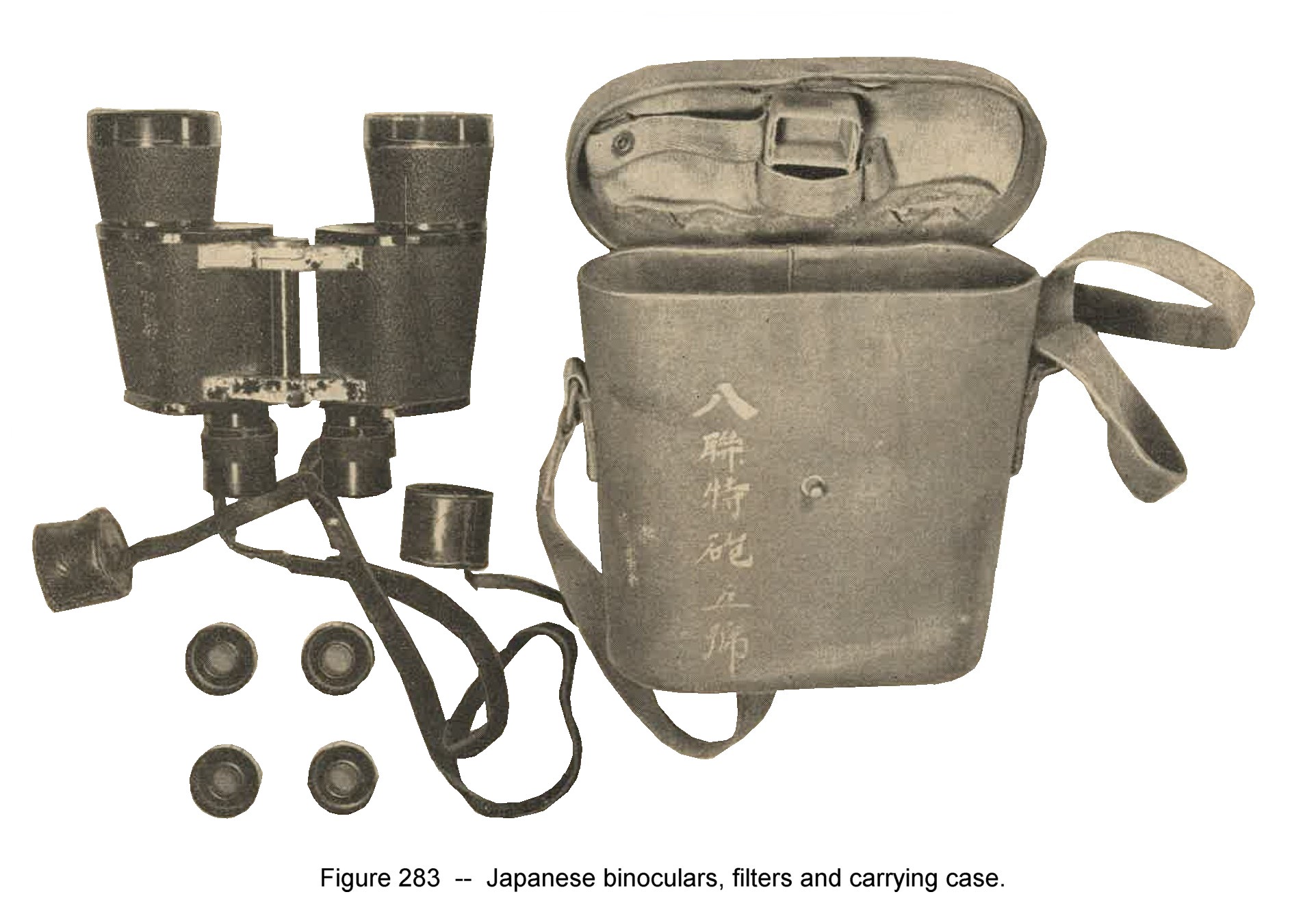
Figure 283. Japanese binoculars, filters, and carrying case. |
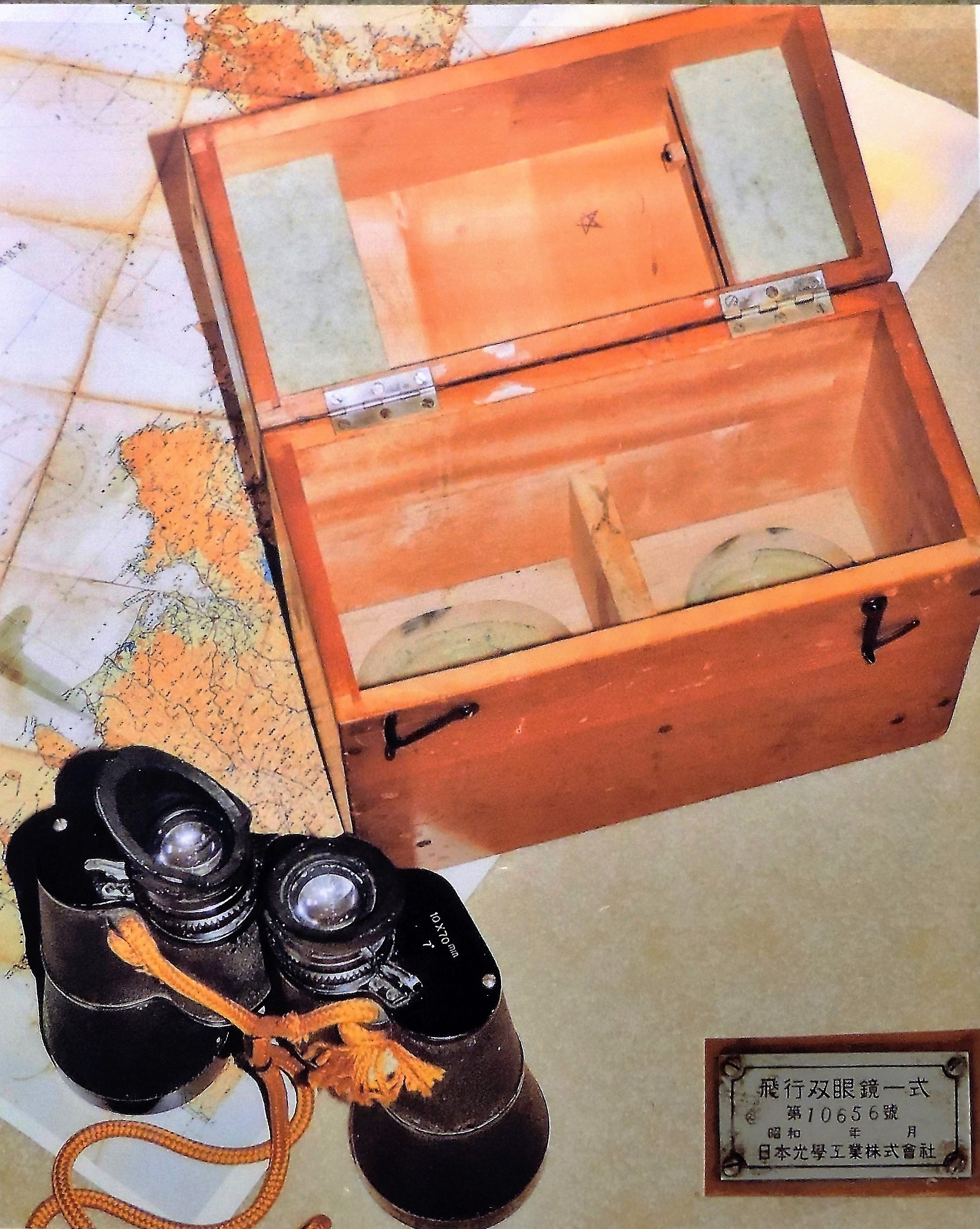
Figure 283-a. Japanese 10 x 70 binoculars, filters, and wooden carrying case. |
| |
|
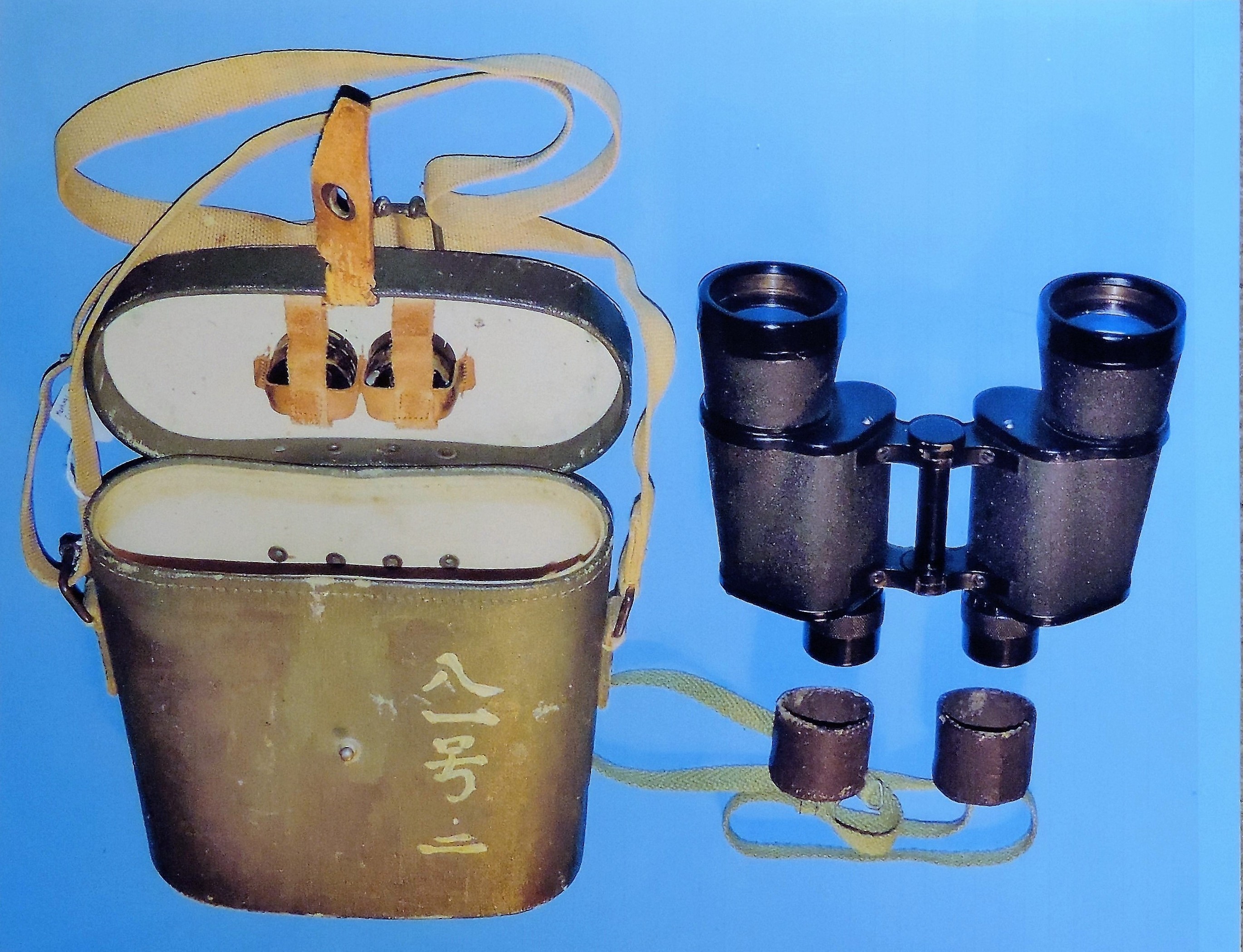
Figure 283-b. WWII Japanese 7 x 50 binoculars, Suzuko, Tokyo. |
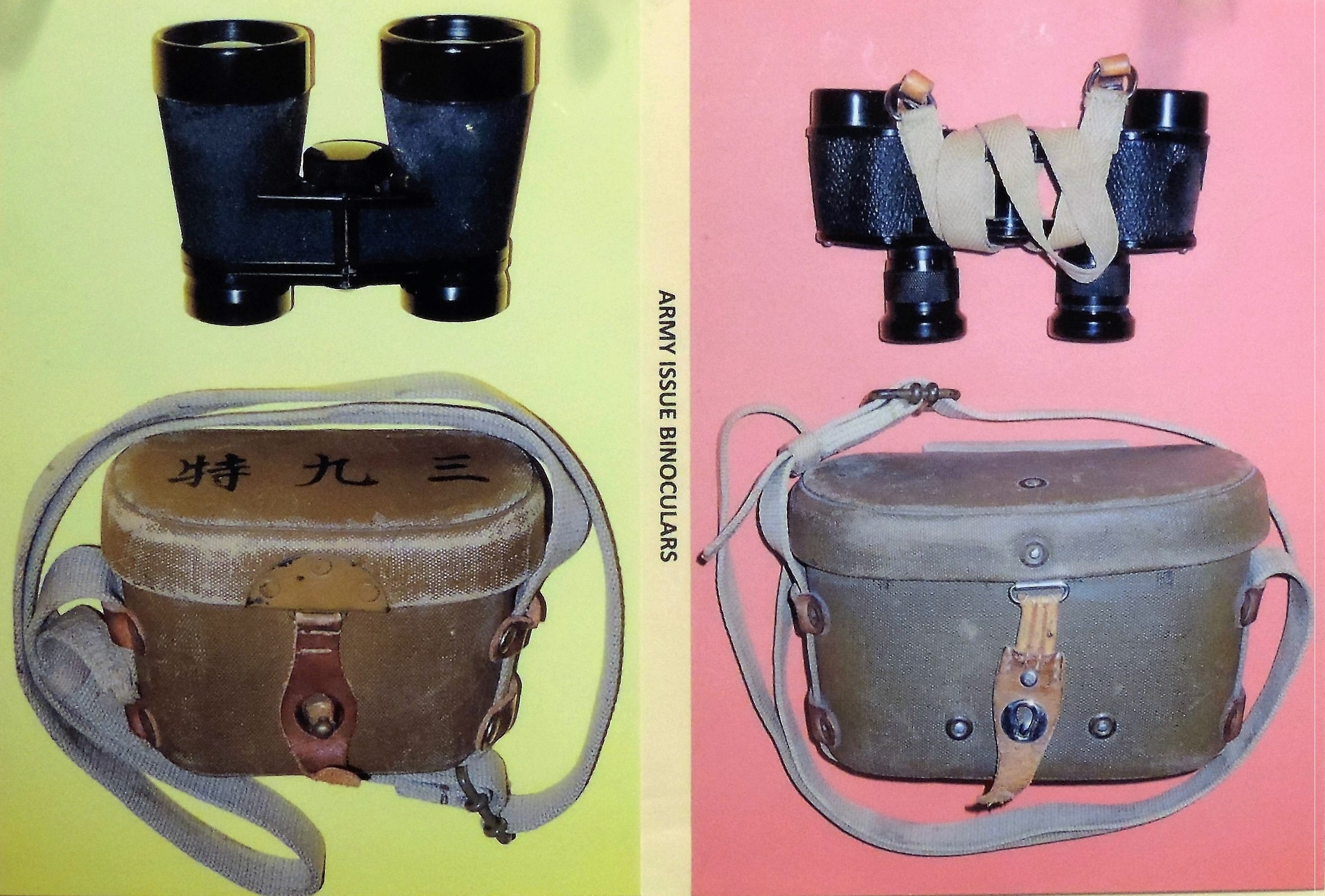
Figure 283-c. WWII Japanese army issue binoculars. |
| |
|
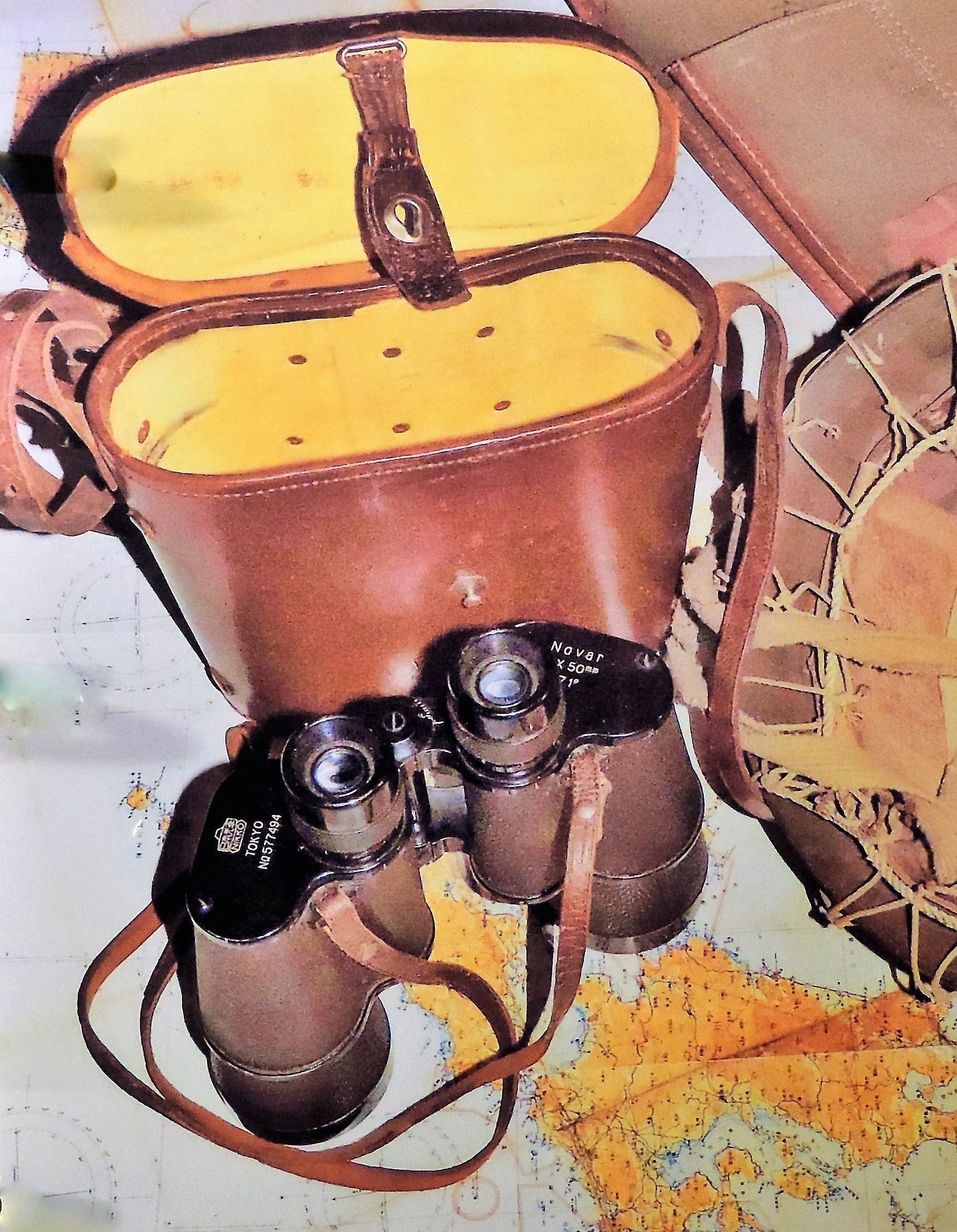
Figure 283-d. WWII Japanese High ranking officer 7 x 50 binoculars. |
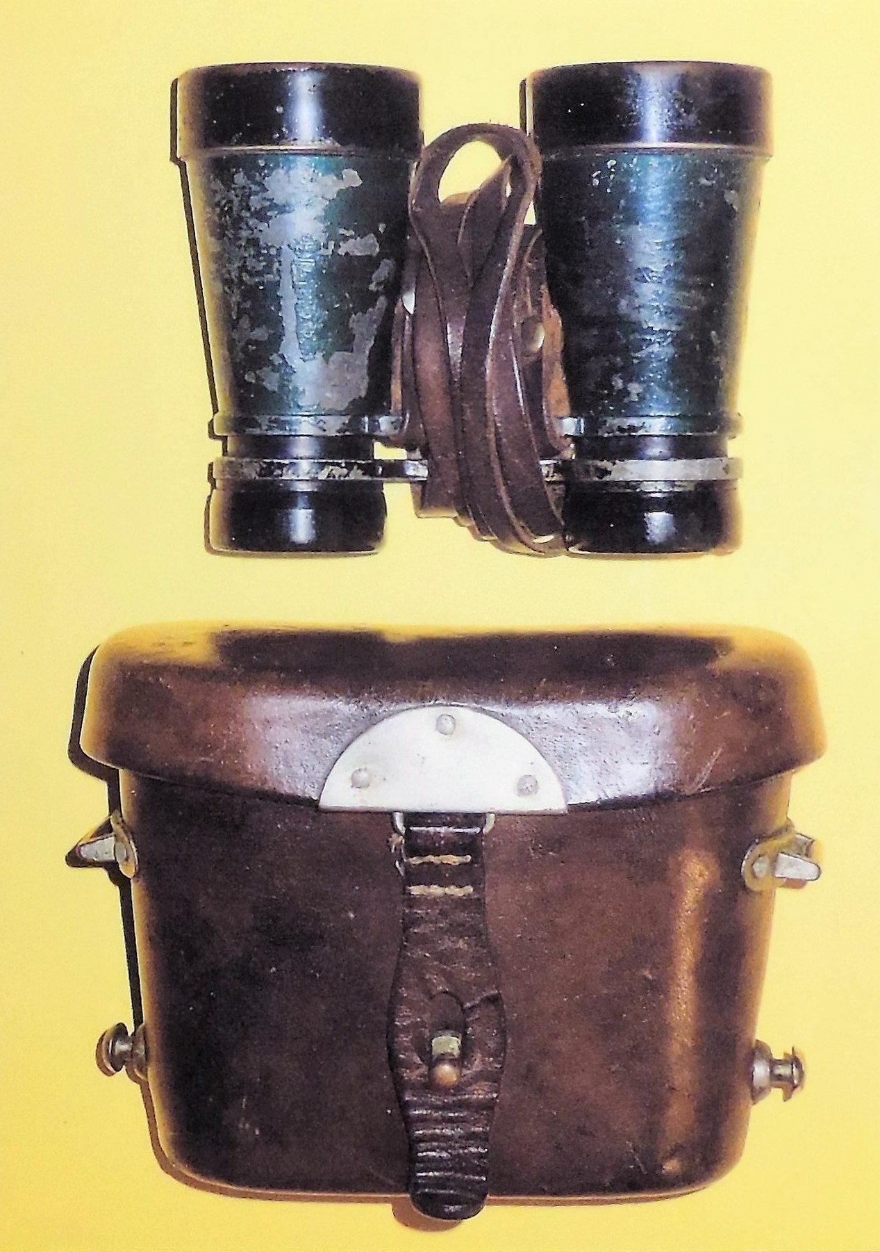
Figure 283-e. WWII Japanese army issue binoculars. |
b. WWII Japanese Periscopes.
Characteristics;
|
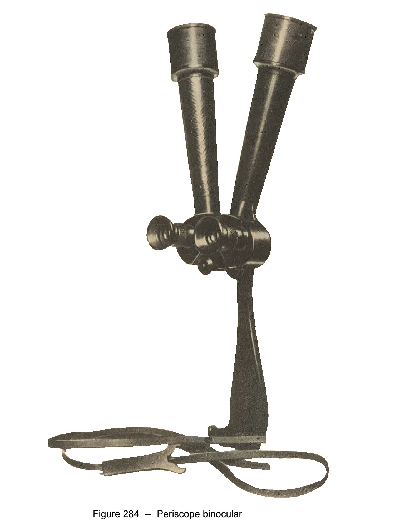
Figure 284. WWII Japanese army periscope binoculars. |
|
Hand held periscope Characteristics;
Figure 285.
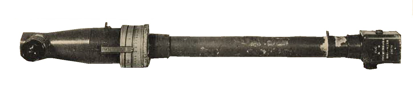
Complete with the carrying case. Figure 285-a This another example of a WWII Japanese hand held periscope. Of metal construction. Black color. High quality optics. A side handle comes as part of the kit. It screwa to the side of the bottom section. The carrying case is of metal construction. It opens at the top. A hinged flap is secured with a single lever. Olive drab color. A cloth shoulder strap is provided. |
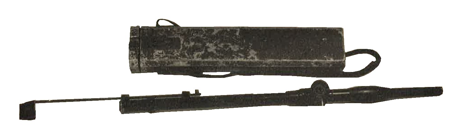
Figure 285. The hand held periscope has a 5 X magnification and 10 degrees field of view. 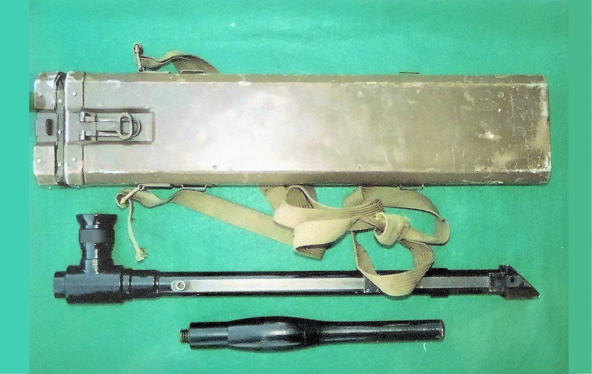
Figure 285-a. Hand held periscope with carrying case. |
a. WWII Japanese Range finders.
|
Figure 286. Model 92 (1932) 40-cm range finder is calibrated for measuring ranges up to 1,500 meters (1,640 yards). It is a coincidence type of range finder with a 4 X magnfication. |
 |
b. WWII Japanese Aiming and laying devices.
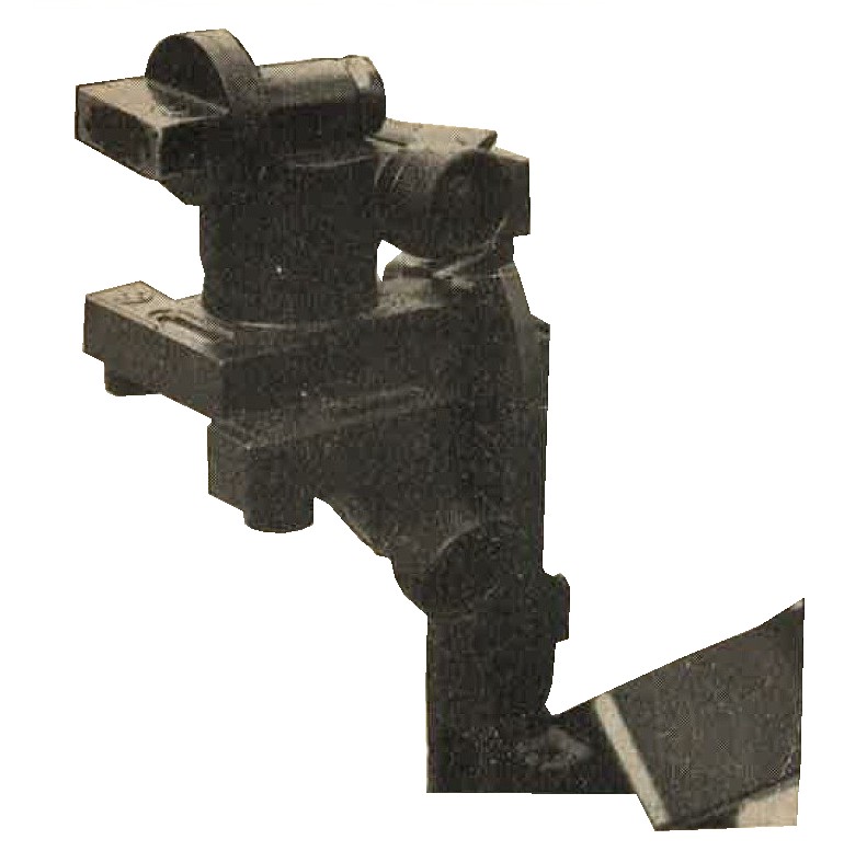
Figure 287. Collimator sight for Model 97 (1937) infantry mortar. Of high quality construction. |
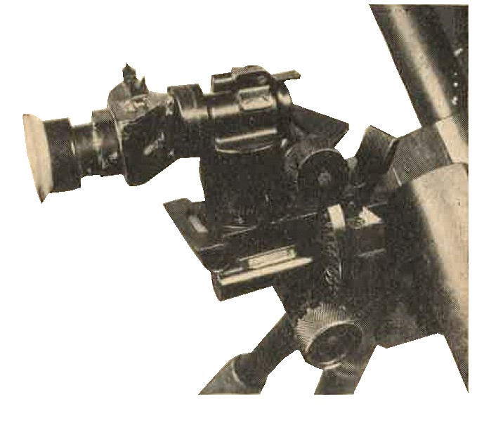
Figure 288. Panoramic sight for Model 94 (1934) mortar. It has a 3 X magnification and a 13 degree field of view. Micrometer drums enable readings to be made to the nearest mil. Very clear, high quality optics. |
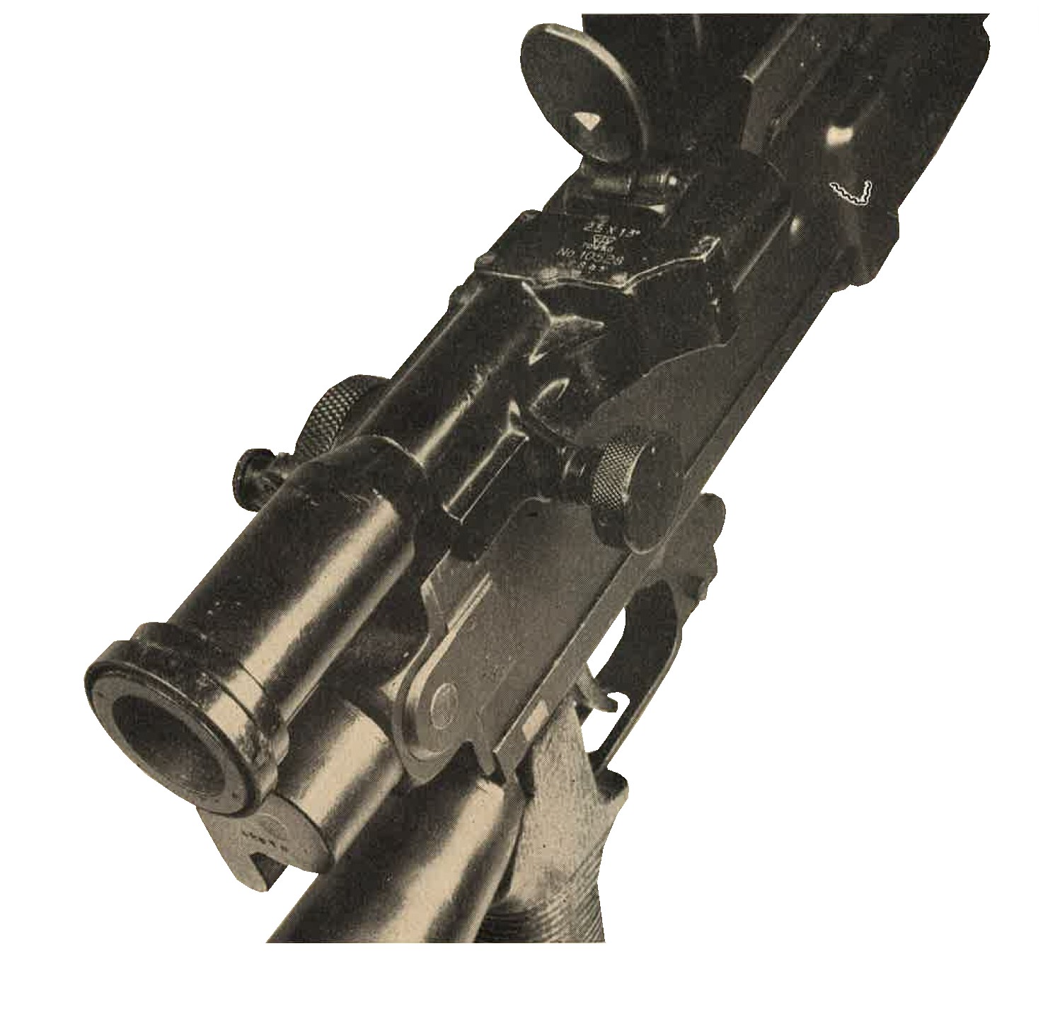
Figure 289. Telescopic sight for Model 96 (1936) 6.5-mm light machine gun. The magnification is 2.5 X, the field of view is 13 degrees, and the weight is 20 ounces. The reticle (graticule) pattern provides for drift and windage, and is calibrated for a maximum range of 1,500 meters (1,640 yards). |
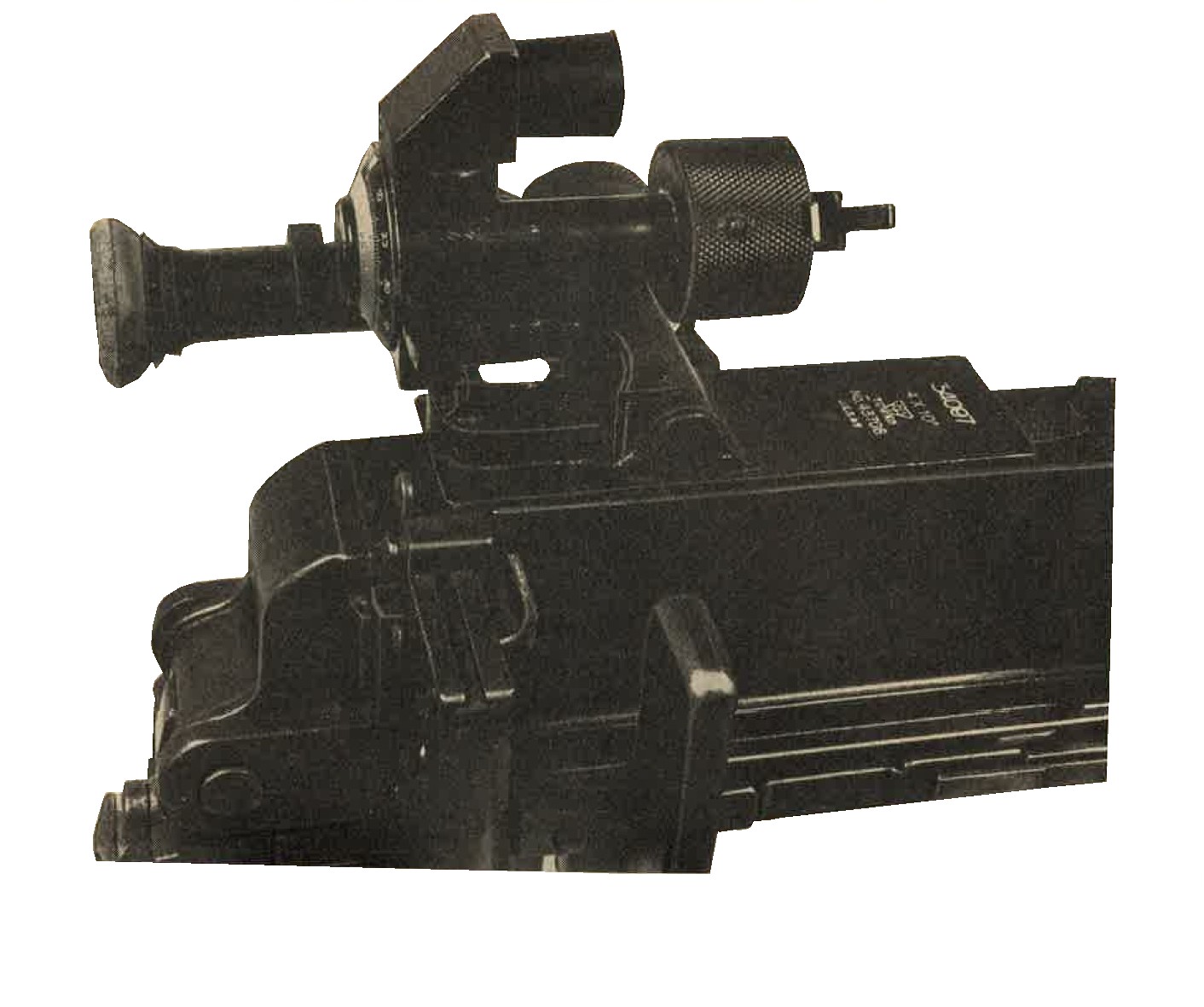
Figure 290. Telescopic sight for Model 92 (1932) 7.7-mm machine gun has a 4 X magnification, a 10 degree field of view, and a weight of 3 pounds, 6 ounces. |
Figure 291. Telescopic sight for the Model 94 (1934) 37-mm gun.
a. WWII Japanese Model 99 (1939) armor shields, portable.
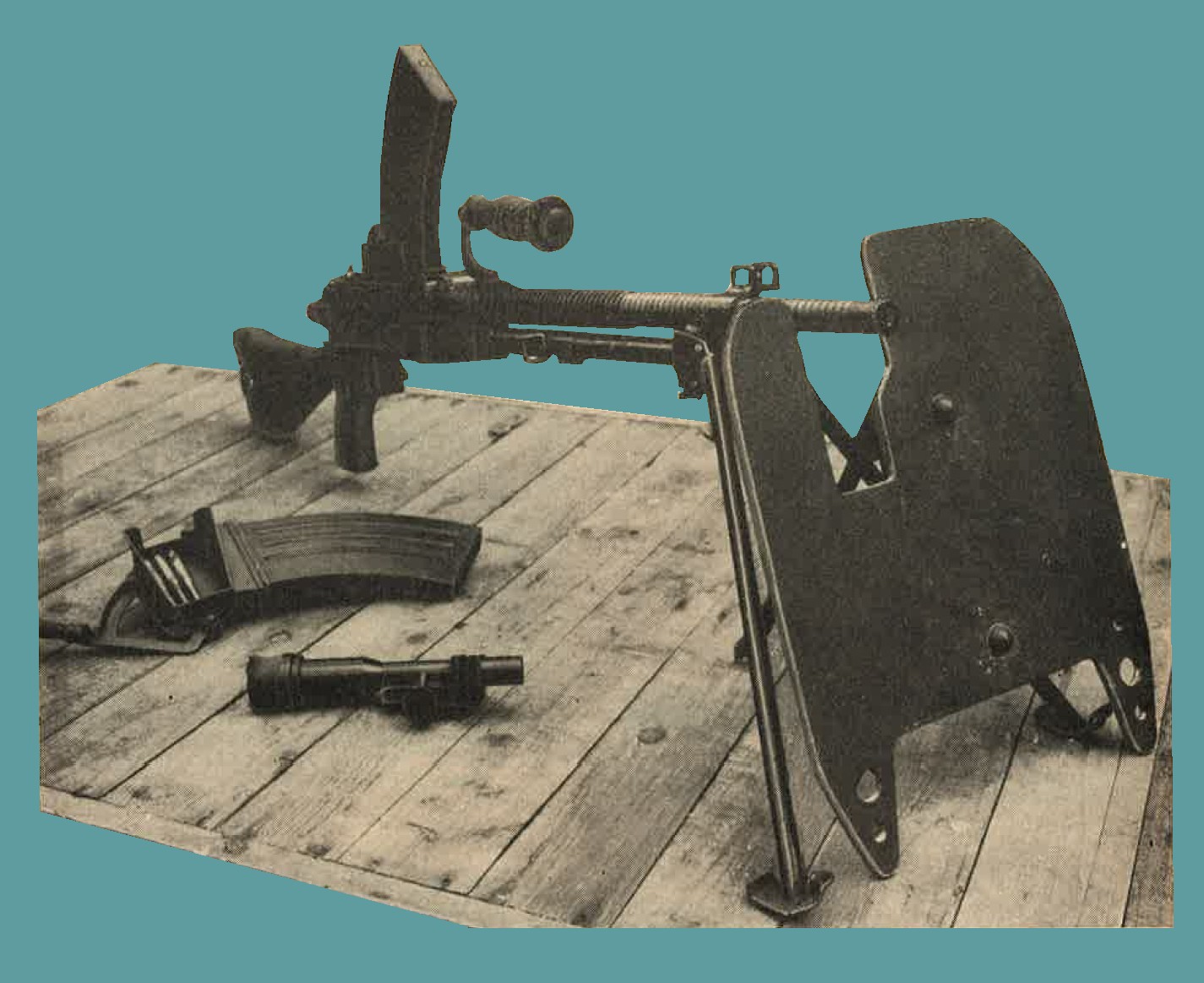
Figure 292.
Model 99 (1939) armor shield with the Model 96 (1936) 6.5-mm light machine gun.
(1) General. While shields are suitable for use in the open, specimens, constructed from what appears to be face-hardened plate, have been found built into the weapon ports of pillboxes. Two sizes have been recovered, the larger measuring 14 x 20 x 1/4 inches (figure 293) and the smaller 12 x 16 x 1/4 inches.
(2) Penetration. Tests have shown that these shields will resist penetration by a .30 caliber ball ammunition at 100 feet. However, some damage may be caused by flaking (chipping). These shields have been penetrated rapidly by .30 caliber AP ammunition as indicated below:
| NUM | RANGE (Yards) | Angle of Impact from Normal | RESULTS |
| 1. | 33 | 10 to 15 degrees | |
| 2. | 100 | 30 degrees | |
| 3. | 200 | Normal | |
| 4. | 500 | Normal |
b. WWII Japanese Army Body armor.
(1) WWII Japanese Bullet proof vest.
The vest (Figure 294) is made from Olive Green drill cloth, with 3 pockets on each side to accomodate armor plates arranged in fish-scale fashion. Characteristics are as follows:
| 1. | Weight complete | --------- | 9 pounds. |
| 2. | Thickness of plates | --------- | 0.08 inch. |
| 3. | Place overlap | --------- | 0.05 inch. |
It is believed that the weight of this vest would preclude its general use by infantry and probably would tend to confine its use to special troops. Tests have shown that the plates are penetrated easily by .303 ball ammunition at 100 yards range, with a 30 degree angle of impact from normal.
(2) WWII Japanese Body protector.
No details are available concerning this body protector (Figure 295), but it is reasonable to assume that it is made from an armor plate of thickness approximating that of the bullet-proof vest. It is possible that the armor plate is in 3 sections for purposes of flexibility.
c. WWII Japanese military Steel helmets.
See Chapter 11.
SECTION III - WWII JAPANESE ARTILLERY EQUIPMENT.
1. GENERAL.
a. Optical instruments.
Optical instruments are cut standing among specimens of Japanese artillery equipment. Examination of them shows good, versatile design, sturdy construction, and satisfactory definition. Knowledge of antiaircraft fire-control equipment is limited; specimens examined to date are obsolescent, although it is entirely possible that much improved designs exist, but have not yet been encountered.
b. Artillery communication equipment.
Artillery communication equipment is described in the signal equipment section of this web chapter. Trucks and other automotive equipment are described in the Automotive and Land Transport section.
c. Although the Japanese army is provided with a variety of prime movers, few types of these have been encountered in forward areas. these have been older models; mode modern types, with improved specifications, well may exist.
2. WWII JAPANESE ARTILLERY FIRE CONTROL INSTRUMENTS.
a. General
Illustrated and described on teh following pages are various examples of artillery fire control equipment used by the Japanese. Their optical equipment is well made, sturdy, and versatile, but none examined differs from standard optical design. Panoramic sights for artillery weapons have not been recovered, but sights for infantry guns and mortars (described in section II) suggest that the Japanese have suitable sights for use on artillery pieces.
b. Off-carriage fire control instruments.
The 75-cm base range finder is an inverted coincidence-type range finder with the following Characteristics;
|
 |
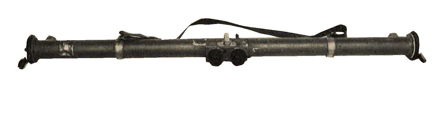 |
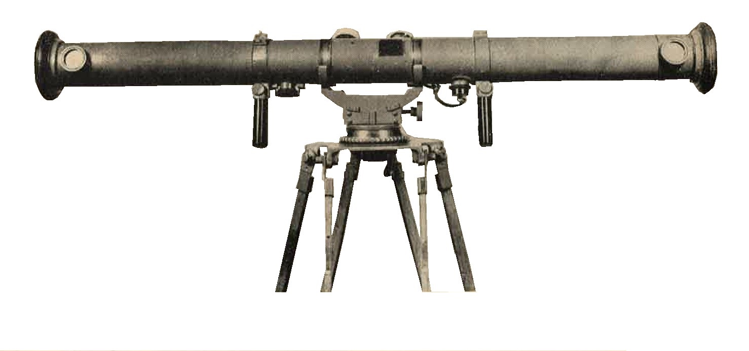
Figure 297. One meter base stereoscopic range finder. The reticle of this instrument is graduated from 250 to 6,000 (presumed to be meters). markings inidcate an 8 degree X magnification, a 45 degree vertical and a 5 degree horizontal field of view. |
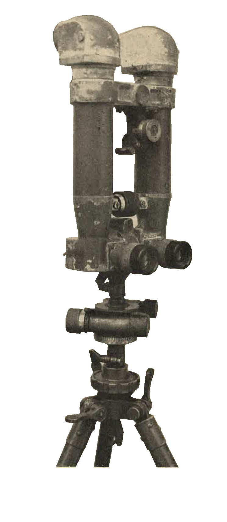
Figure 298. The Model 93 battery commander's telescope permits measurement of angle of site from -300 to +300 mils, as well as measurement of azimuth. An unusual feature is that the telescopes cannot be placed in a horizontal plane for betetr stereoscopic vision. It has an 8 X magnification and a 6 degree field of view. |
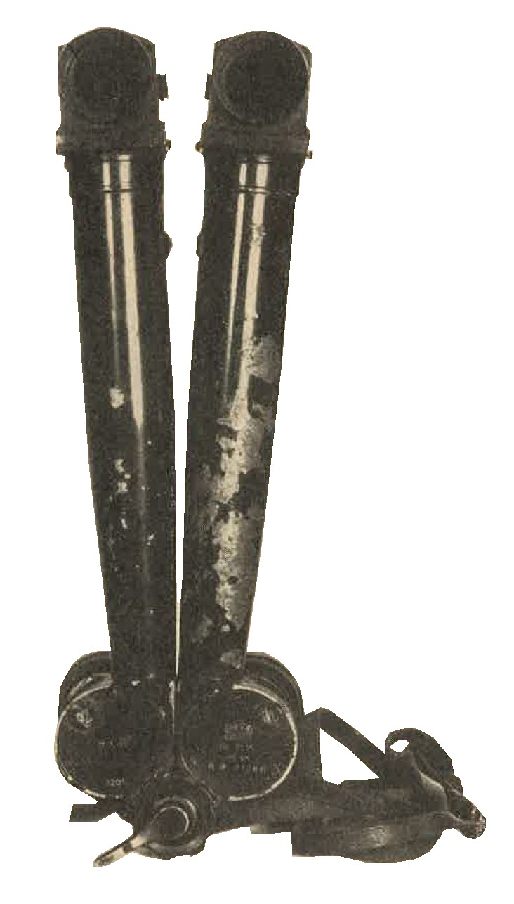
Figure 299. this batery commander's telescope has an 8 X magnification and a 6 degree field of view. It is constructed so that the telescopic arms may be placed in a horizontal position for better stereoscopic vision. |
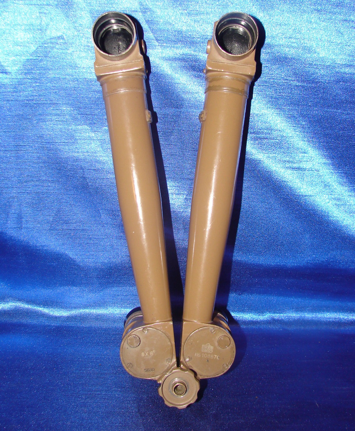
Figure 299-a. WWII Japanese artillery periscope.
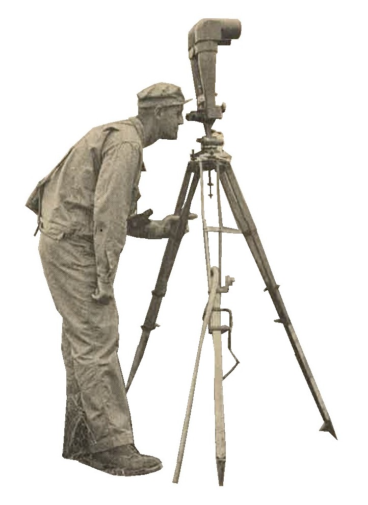
Figure 300. Battery commander's telescope. Although giving a high magnification and wide field of view, the individual telescopes cannot be placed in a horizontal position to improve stereoscopic vision. |
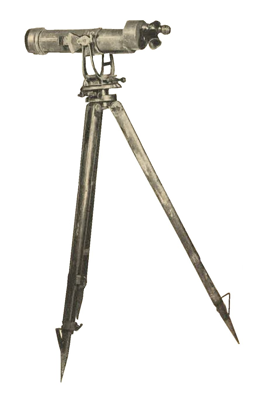
Figure 301. This artillery spotting telescope may be used with three different eyepieces, each of which gives a different magnification, the maximum being 33 power. Provisin is made to measure azimuth, and elevation (from -30 degrees to +30 degrees). |
c. WWII Japanese Aiming and laying devices.
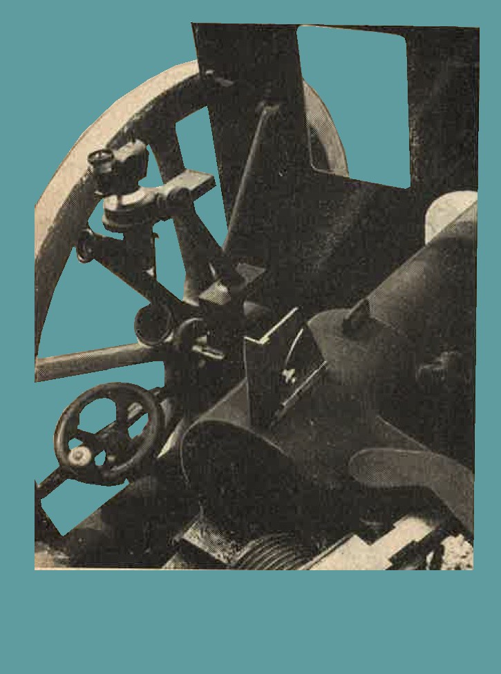
Figure 302. This panoramic sight appears to have been designed for use on more than one artillery piece. It is shown above mounted on the Model 41 (1908) infantry gun. The sight has a 3 X magnification and a 13 degree field of view. |
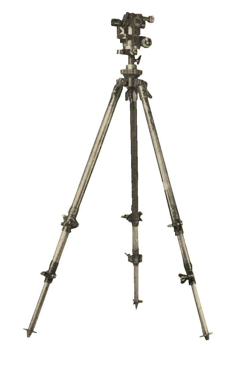
Figure 303. This aiming circle has a 4 X magnification and a 10 degree field of view. Similar to the American aiming circle, it is used by artillery units for measuring angles in azimuth and site, and for general topographical work. |
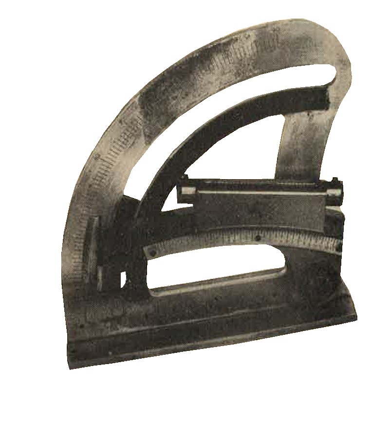
Figure 304. This gunner's quadrant is calibrated from 0 to 90 degrees, with a vernier reading to 1/16 of a degree. |
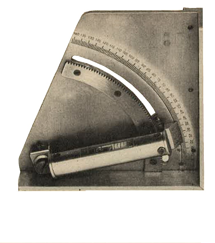
Figure 305. This gunner's quadrant is calibrated in units of 10 mils, extending from 0 to 1,410 mils (79 degrees). A vernier scale enables adjustments to the nearest mil. It is considered possible that this quadrant has been designed primarily for use with the Model 41 (1908) 75-mm infantry gun. |
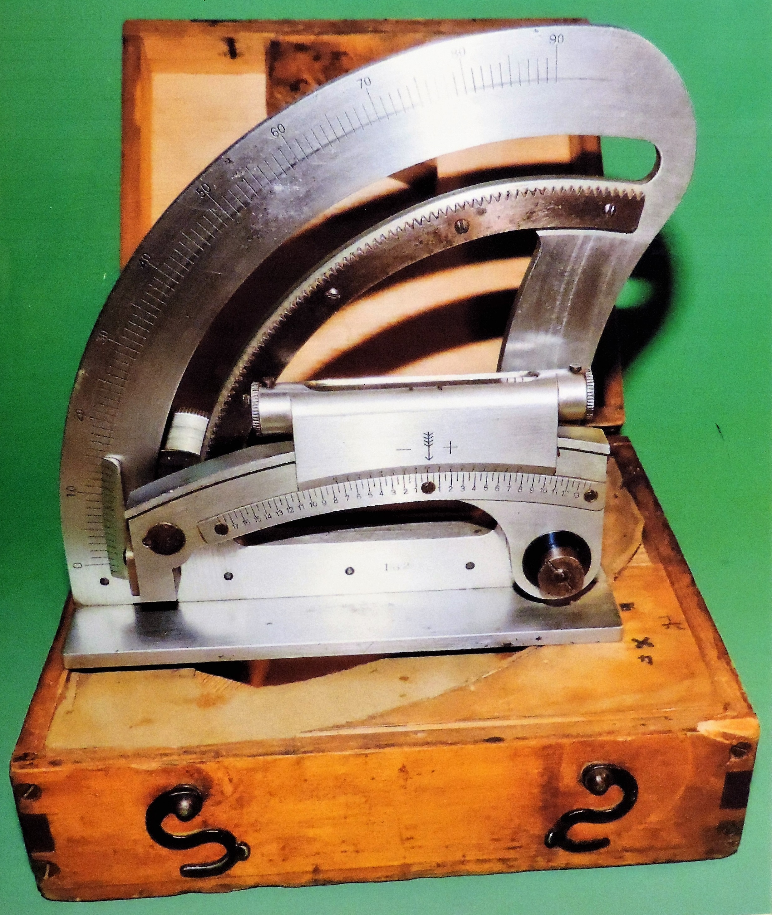
Figure 304-a. WWII Japanese artillery quadrant with carrying case.
3. WWII JAPANESE ANTIAIRCRAFT FIRE CONTROL EQUIPMENT.
a. Automatic weapons. The Model 92 (1932) 7.7-mm and the single mounted Model 93 (1933) 13-mm machine guns, described in Chapter 9, are provided with antiaircraft ring sights. The latest type ring sight recovered, illustrated in Figure 306, is rotated automatically around its horizontal axis as the gun is elevated. It is believed that the purpose of this design is to correct automatically for the angle of approach.
The following automatic weapons are provided with more complex sights than the ring sights.
(1) Dual mounted Model 93 (1933) 13-mm machine gun. To date (1944) only incomplete sights (Figure 307) have been examined on dual mounts. They are constructed in such a manner that estimates of target course and speed are fed into the instrument, which then applies the appropriate deflection to the sighting telescope. The sight would appear to require 3 men for its operation.
(2) Japanese Model 98 (1938) 20-mm automatic cannon.
Complete antiaircraft sights for this weapon have not yet been recovered. It is known that some form of computing sight is used.
(3) Japanese Model 96 (1936) 25-mm automatic cannon.
A computing sight, similar to the one described in a (2) for the 13-mm machine gun, is provided for this weapon (Figure 308).
(4) Japanese Vickers Tpe 40-mm automatic cannon.
This weapom also has a computing sight for use in antiaircraft fire. In addition, an automatic fuze setting mechanism is provided. The time setting given to each fuze is adjujted, thru a complex series of gears and linckages by the manipulation of the gun in elevation and depression.
b. Heavy antiaircraft weapons.
According to modern standards the Japanese heavy antiaircraft fire control equipment seen to date has been outmoded and designed for use with the Model 88 (1928) 75-mm antiaircraft gun. Off-carriage fire control instruments and computing mechanisms used with these guns are as follows:
(1) 2-meter base height and range finder. This instrument (Figure 309) is of good optical construction and standard, but most specimens recovered had no provision for electrical data transmission. It supplies the "present attitude" to the guns.
(2) Target speed and course angle calculator. This instrument (Figure 310) is mounted on a tripod for use. The illustration in Figure 310 does not include an elbow telescope, which must be mounted on its top in order to operate the instrument. The calculator supplies the angle of approach (course angle) of the target at the present position and ground speed of the target.
|
(3) Corrector scale. This is a metal board (Figure 311)on which may be read mechanically the correction
angles required for wind direction and powder temperature.
(4) Spotting binoculars. These are used to obtain spot corrections, and have 15 X magnification and 4 degrees field of view (Figure 312). Data from each of the instruments shown in figures 309, 310, 311, and 312, are shouted to the gun crew, certain individuals of which operate the "on carriage" components. This procedure theoretically results in the gun being correctly aimed and the time fuzes being so adjusted that the projectiles burst on the target. The "on carriage" components are: (a) Elevation computing apparatus. (b) Azimuth computing apparatus. (c) Auxiliary elevation and lead correction disc. (d) Fuze setter. |
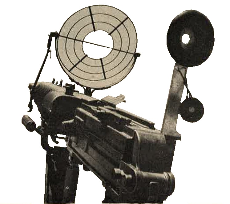
Figure 306. Front and rear antiaircraft sights mounted on the Model 92 (1932) 7.7-mm machine gun. |
c. WWII Japanese artillery Computing director.
A few data computing directors have been captured, and provision for electrical data transmission has been seen on height finders. Mounting surfaces for data receivers have been found on some Model 88 (1928) 75-mm antiaircraft guns. There is evidence of more general use of electrical data transmission and computing directors than would be indicated by the equipment captured to date (1944).
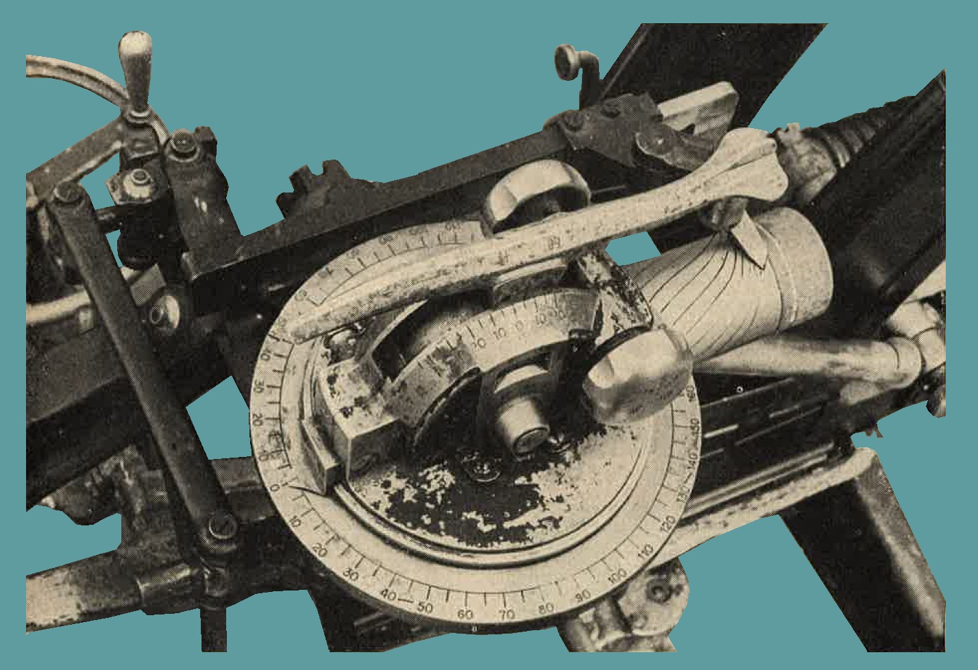
Figure 307. -- Computing head for antiaircraft sight used on dual mounted Model 93 (1933) 13-mm machine gun.
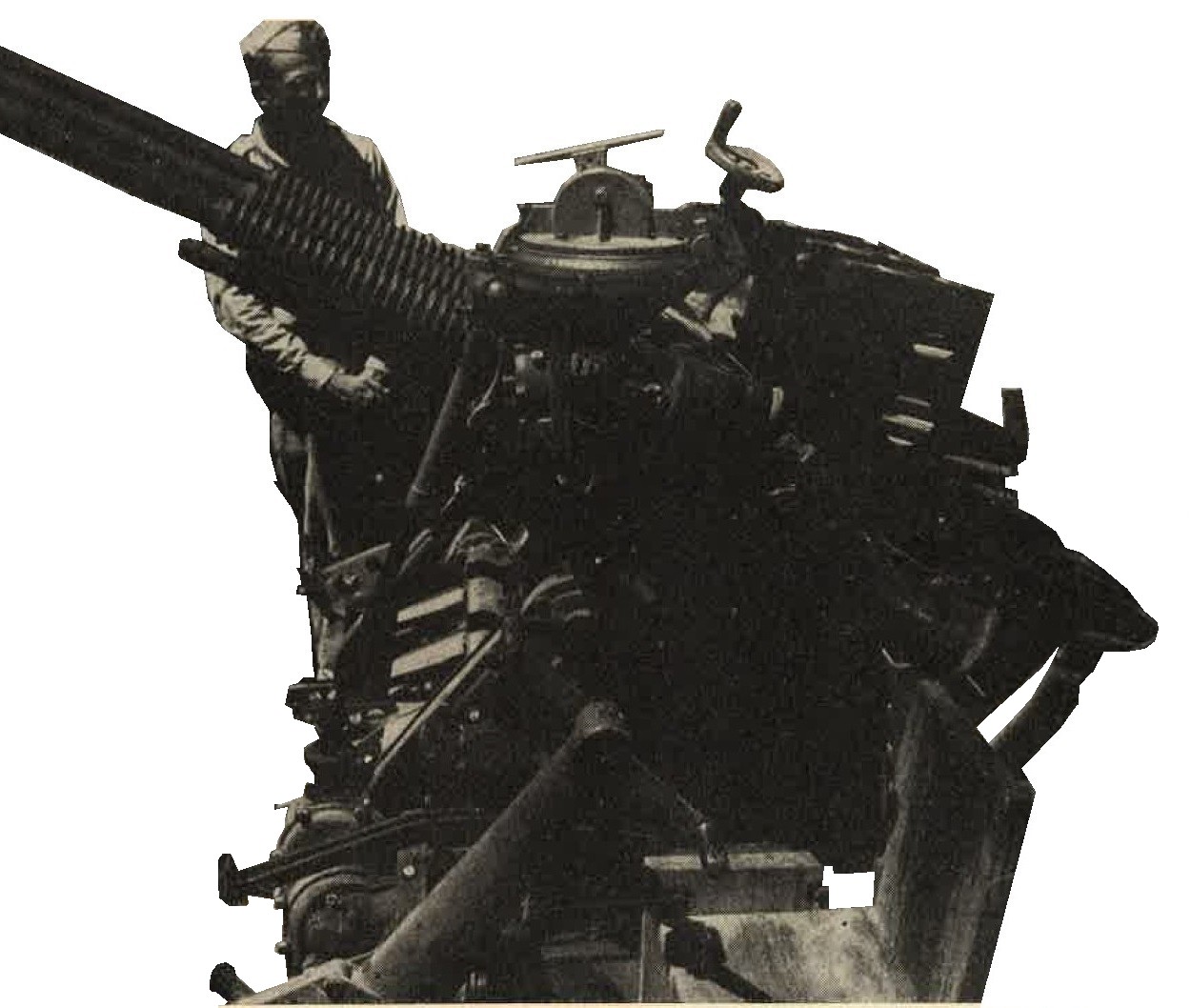
Figure 308.
Computing sight for Japanese Model 96 (1936) 25-mm automatic cannon.
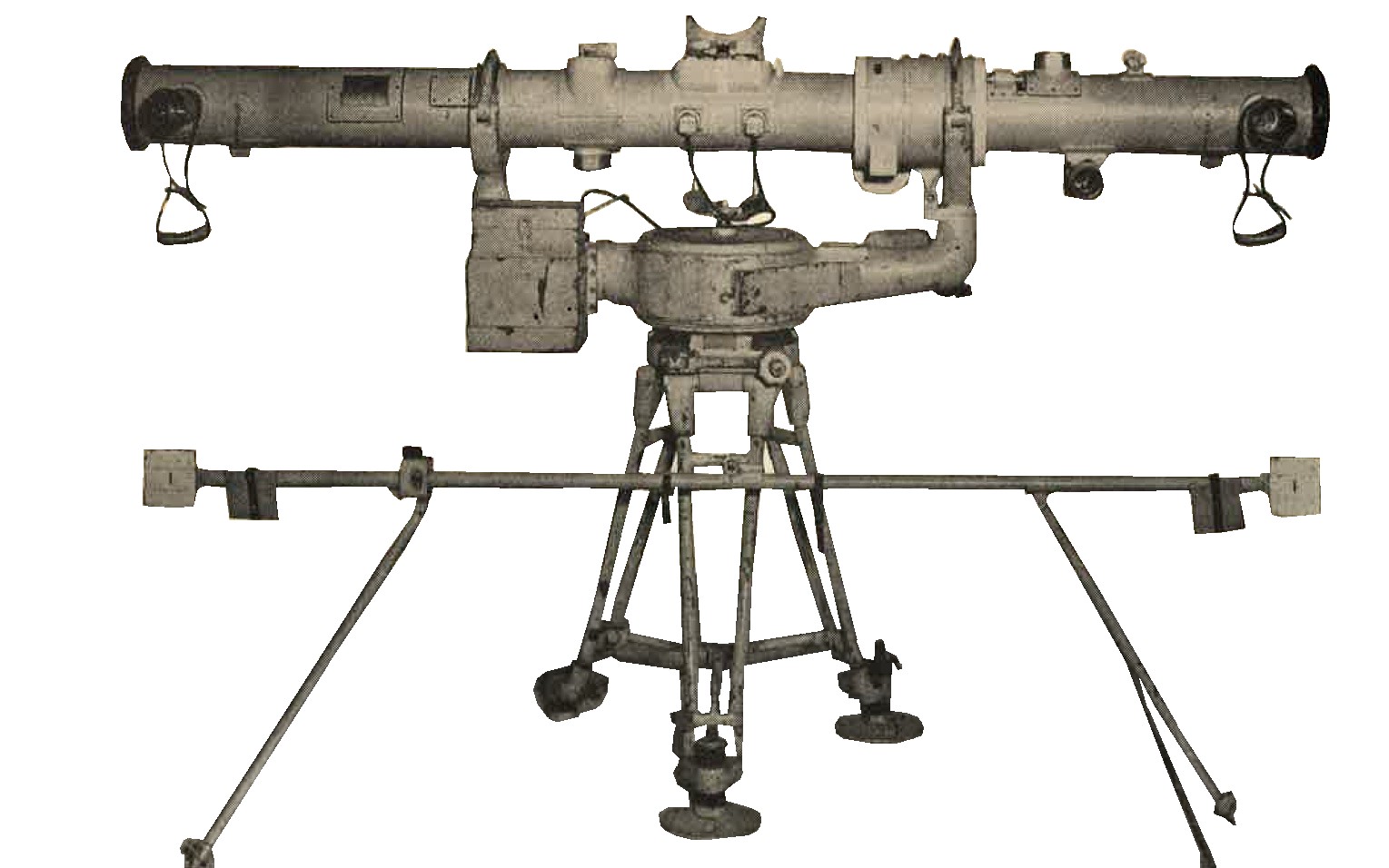
Figure 309. -- 2 meter base height and range finder. |
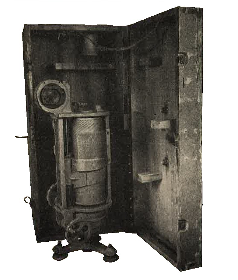
Figure 310. Target speed and course angle calculator with carrying box. |
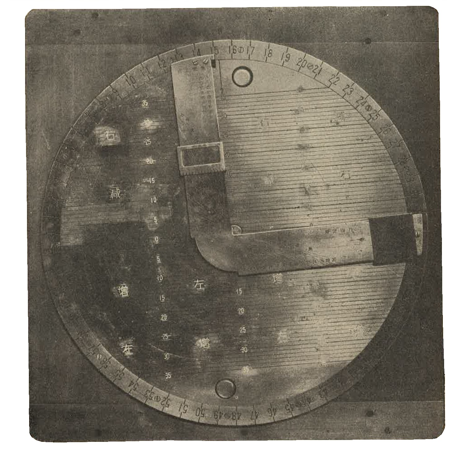
Figure 311. Powder charge temperature and wind correction scale. Circular shape with Japanese writing on the face. |
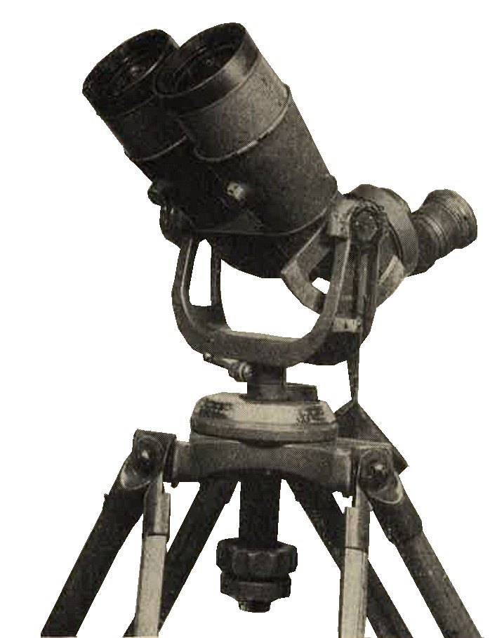
Figure 312. Model 89 (1929) 10-cm antiaircraft (AA) spotting binoculars. Very nice quality. Clear optics. |
d. WWII Japanese Searchlights.
Japanese searchlights include the following sizes:
60-cm (23.6 inches).
90-cm (35.4 inches).
98-cm (38.6 inches).
100-cm (39.4 inches).
110-cm (43.3 inches).
150-=cm (59.1 inches). (Figure 313)
The following equipment is used by Japanese searchlight units:
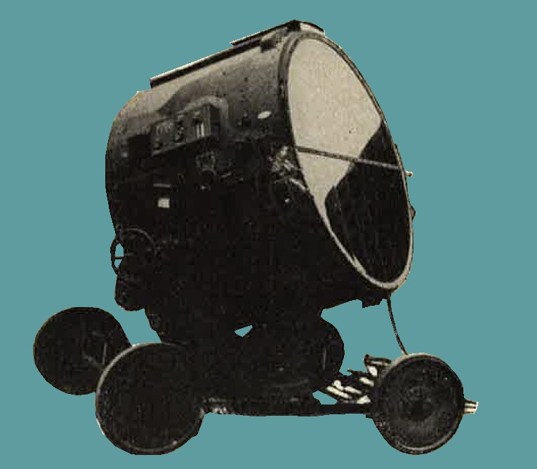
Figure 313. 150-cm searchlight. |
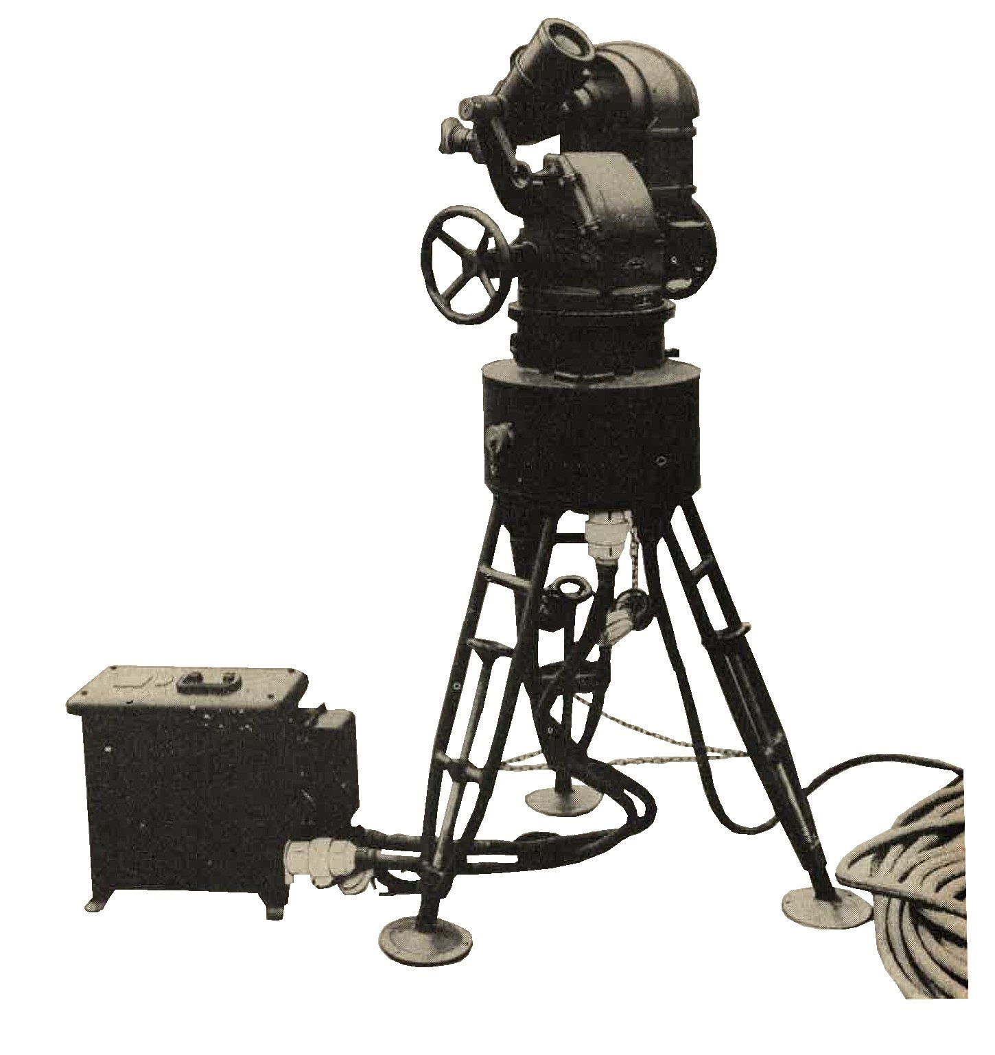
Figure 314. Searchlight comparator. |
(1) Generator truck (standard 2-ton truck chassis).
(2) Searchlight comparator. The searchlight comparator illustrated in Figure 314 is an instrument with which an observer, by keeping a plane in the crosslines of the telescope, automatically directs the searchlight on the plane. It was found satisfactory for operation of U.S. searchlights.
(3) Sound locator. Several varieties of Japanese sound locators are known to exist. One of teh small models is illustrated in Figure 315.
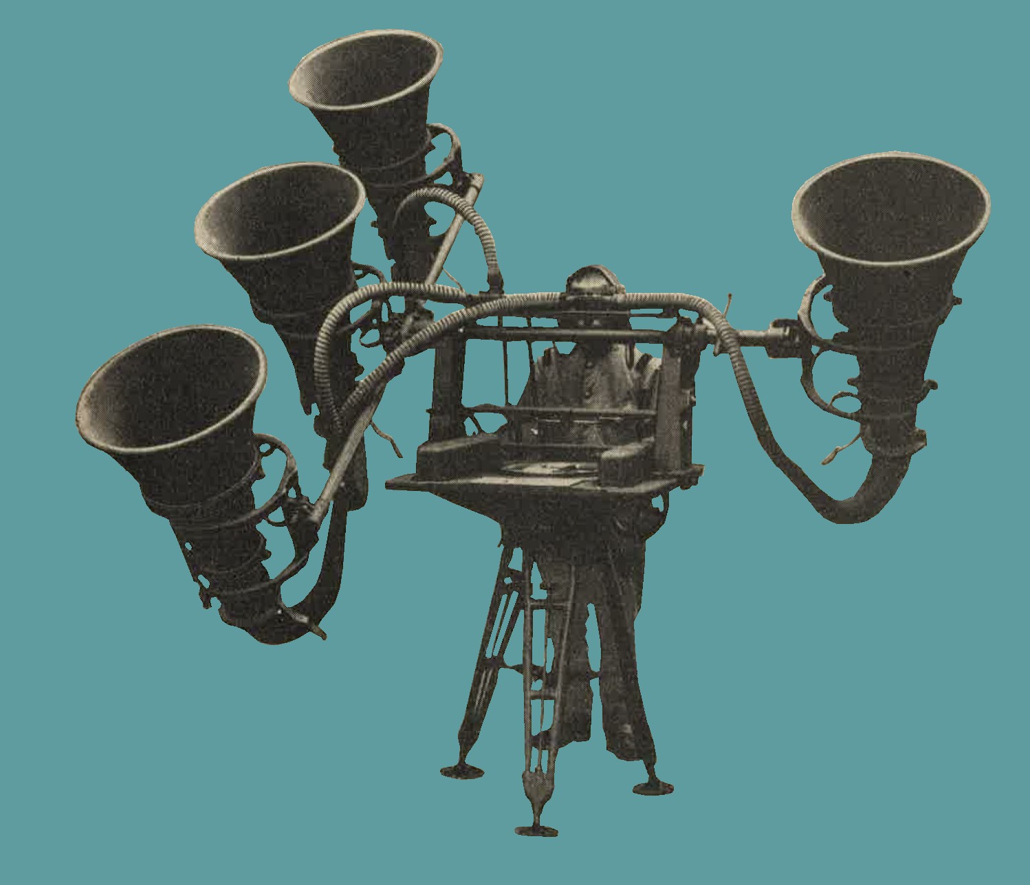
Figure 315.
Small sound locator.