Donate
| Chapter | 4. | BIVOUAC EQUIPMENT | ||
| Poncho | 23 | 16 | ||
| Poncho Liner | 24 | 19 | ||
| Shelter Half | 25 | 20 | ||
| Sleeping Bag | 26 | 21 | ||
| Sleeping Bag cases | 27 | 22 | ||
| Arctic Sleeping bag | 28 | 25 | ||
| Pneumatic Mattress | 29 | 25 | ||
| Blanket | 30 | 26 | ||
| Chapter | 5. | LOAD CARRYING EQUIPMENT | ||
| Lightweight Load-Carrying Equipment | 31 | 27 | ||
| Universal Load-Carrying Sling | 32 | 35 | ||
| Packboard | 33 | 37 | ||
| Mission Loads | 34 | 41 | ||
| Lightweight Rucksack | 35 | 41 | ||
| Grenade Carrier Vest | 36 | 43 | ||
| Bags | 37 | 43 | ||
| Chapter | 6. | MISCELLANEOUS CLOTHING AND EQUIPMENT | ||
| Identification (ID) Tags and Necklace | 38 | 46 | ||
| First Aid Packet | 39 | 46 | ||
| Compass | 40 | 46 | ||
| Waterproof Matchbox | 41 | 46 | ||
| Field Protective Mask (M17A1) | 42 | 46 | ||
| Entrenching Tool | 43 | 47 | ||
| Bag and Case Carrying Sling | 44 | 47 | ||
| Canvas Cot and Insect-Bar Frame | 45 | 47 | ||
| Insect bar | 46 | 47 | ||
| Hat and Mosquito Netting | 47 | 48 | ||
| Multipurpose Net | 48 | 48 | ||
| Knitted Wool Scarf | 49 | 49 |
23. Poncho. The poncho, with hood, is made of coated nylon cloth and is waterproof. It is roughly rectangular in shape with the long sides parallel and the short sides slightly curved. The hood and the opening for the neck are located at the center of the rectangle. A drawstring is provided at the hood.
a. Use.
Use the poncho as a rain garment, shelter, ground cloth, and sleeping bag.
(1) Rain garment.
The poncho may be worn as a rain cape with the arms inside (fig 13), or it may be worn with the arms outside for freedom of movement. To put on the poncho, slip it over the head. If the poncho hood is to be worn, adjust the hood drawstring to fit. The helmet and/or liner are wool over the hood. Fasten the snap fasteners together on each side of the poncho. To prevent the poncho from flapping in high winds, make certain all fasteners are fastened. Note. The poncho may not be suitable or adequate for certain personnel under varied conditions. If this is the case, the user may use the wet-weather parka and the wet-weather overalls (para 20).
(2) Sheltters.
Various types of shelters and "lean to" may be made by attaching ponchos to trees, tree branches, bushes, sticks, or poles. Always dig a ditch under the eaves of the shelter to drain off rainwater which dips from the edges of the poncho.
(a) Individual shelters. The poncho, with the hood closed, may be pitched as a one-man shelter (fig 14), or it may be attached to another poncho and pitched as a two-man shelter (fig. 15).
(b) Miscellaneous shelters.
Two or more ponchos (fig 16) may be attached to each other to form various types of shelters. (3) Ground cloth. The poncho may be used as a ground cover for shelters and as a waterproof barrier between the ground and sleeping bag (fig 17).
(4) Sleeping bag.
The poncho may be used as a sleeping bag either by itself or in conjunction

Figure 13. Poncho worn as a rain garment.
with a blanket or the poncho liner (fig 18). Spread the poncho flat on the ground, making sure the hood opening is tightly closed. If a blanket is used place it on the top of the poncho, fold the poncho and blanket in half lengthwise, and fasten the snap fasteners together. To attach the poncho liner to the poncho, refer to paragraph 24.
If the poncho is used without a blanket or liner, snap the sides together along their entire length, and tuck the foot end under to keep the feet from sticking out. Caution. Do not fasten the snap fasteners together when the poncho is used as a sleeping bag in combat areas; it cannot be opened quickly.

Figure 14. One man shelter tent. using one poncho.

Figure 15. Two man shelter tent. using two ponchos.
b. Folding and Packing.
The poncho can be folded for carry with individual load-carrying equipment or for carry over the individual equipment belt. It can be folded in any appropriate manner and carried in the duffel bag or the field pack if space permits, but care should be taken not to damage it in folding or by pressing it against sharp or rough objects in the pack or bag.
(1) To fold the poncho for carry with individual load-carrying equipment, refer to figure 19, and proceed as follows:
(a) Lay the poncho out flat (1) with the identification label up. Pull the hood through the neck opening, and flatten it toward either curved side.

Figure 16. Miscellaneous poncho shelters.
(b) Bring both curved edges of the poncho toward the neck opening until the center grommets of the curved sides overlap (2).
(c) Fold the edge nearest to you back over the overlap to a point 10 inches from the opposite side (3).

Figure 17. Poncho used as a ground cover.
(d) Fold the edge nearest to you over to align with the opposite edge (4). At this point, the fold should be about 15 inches wide.
(e) Starting at either short side, roll the poncho tightly into one fold toward the opposite end past the midway point (5).
(f) Overlap the opposite end about 7 inches (6), and open the first fold of this end.
(g) Continue rolling (7), and insert the roll into the fold (8) to form an envelope roll.
(h) Carry this roll under the pack as shown in figure 19.
(2) To fold the poncho for carry over the individual equipment belt, proceed through step (d) above, and then-
(a) Make one additional fold in the same direction.
(b) Fold in half from left to right.
(c) Fold in half again from left to right. This should result in a folded poncho about 8 inches wide and 17 inches long.
(d) Fold this over the back of the pistol belt and tie around the bottom with a string, shoelace, or rubber band, as shown in figure 20.

Figure 18. Poncho used as a sleeping bag.

Figure 19. Folding poncho for carry with individual load-carrying equipment.
c. Repairing. If leaks develop, turn in the poncho for repair or salvage.
24. Poncho Liner
a. Description. The poncho liner conforms in size and shape to the poncho (para 23). It is made of polyester batting sandwiched between two panels of camouflage-patterned, light nylon fabric. The liner is equipped with eight tie tapes.
b. Use. Use the liner as a blanket, or use it with the poncho as a sleeping bag. To attach the poncho liner to the poncho (fig 21), proceed as follows:
(1) Spread the poncho on the ground, making sure that the hood opening is tightly closed and is on the underside.
(2) Place the liner on the poncho, matching the tie tapes on the liner with the grommets on the poncho, and tie the poncho and liner together.
(3) Fold the poncho and liner in half lengthwise, and fasten all snap fasteners along the long side. Caution. Do not fasten the snap fasteners when the poncho sleeping bag is used in combat areas, because it cannot be opened quickly.

Figure 20. Carrying poncho over individual equipment belt.

Figure 20a. Carrying poncho over individual equipment belt - Rear view.
(4) Tuck the foot end under to keep your feet from protruding.
25. Shelter Half.
The shelter half is made of water-repellent, mildew- resistant cotton and rayon duck. It is 154 1/4 inches long and has triangular flaps at both ends. It is issued to your with five tent pins, a guy line, and a three-section tent pole. The shelter half, when joined to another by snap fasteners, forms a shelter for two men. The tent is ventilated by opening one or both ends. The shelter half may be used by itself as a fly for shade and shelter.
a. Two-Man Tent.
(1) Pitching.
Two men can pitch the two man tent in 5 minutes as follows:
(a) Spread two shelter halves on the ground, one with the snap fasteners up and to the center, and the other with the snap fasteners down and to the center.
(b) Proceed as shown in figure 22.
(2) Striking.
(a) Open enough snap fasteners so that the tent poles can fall to the ground.
(b) When the tent poles are down and the tent is flat, remove the pins, unfasten all remaining snap fasteners, disassemble the poles, and untie the guy lines from the loops at each end of the tent.
c. Folding.
To fold the shelter half, refer to figure 23, and proceed as follows:
(1) Spread the shelter half out flat with the button side down. Place tent pole sections, pins, and guy lines in the center of the wide side of either triangular end (1).

Figure 21. Poncho liner with poncho.

Figure 22a. Procedure for pitching shelter half tent.

Figure 22c. Procedure for pitching shelter half tent - Continued.

Figure 22b. Procedure for pitching shelter half tent - continued.
(2) Fold the triangular ends toward the center with the pointed ends overlapping (2).
(3) Working at either unfolded side, fold lengthwise, bringing the edge over one-third of the width of the shelter half (3). Fold the other unfolded side over in the same manner.
(4) Starting at the end where the tent pole sections were placed, roll the shelter tightly and evenly until about 6 inches from the end ( 4).
(5) Fold back all plies except the bottom ply on the opposite end to form a pocket or envelope. Tuck the rolled portion into the envelope (5).
d. Carrying.
Carry the rolled shelter half under the expendable flap of the field pack, attached to the bottom of the field pack, or carry it inside the duffel bag.
26. Sleeping Bag
a. Description. The M-1949 mountain sleeping bag (1. fig 24) is a mummy-shaped bag made with overlapping channels filled with a mixture of waterfowl feathers and down to provide the necessary insulation. The shape and design of the bag give maximum warmth with minimum weight.
The free-running slide fastener at the front opening of the bag has a webbing loop attached to the slider for ease of operation. Tie tapes at the foot of the bag are used to secure the bag when it is rolled. The sleeping bag case (2) covers the outside of the sleeping bag to provide a water-repellent outer layer for protection from moisture, weal', and soiling. The bag, with case, is intended for use in areas where the temperature ranges from 14 to 45 degrees F.
b. Care and Use.
(1) Keep the bag dry as possible; always use the water-repellent, sleeping-bag case over the sleeping bag. Although the case is water repellent and will protect against moisture, you should select the driest ground possible and keep the bag out of the rain, if possible.
(2) Breathe through the face opening to prevent your breath from wetting the bag. Do not put your face inside the bag. If your face is cold, cover it with a muffler, coat, or towel. When you get up, open the bag wide, and fluff out the moist warm air.
(3) Do not wear damp clothing and avoid perspiring unnecessarily while in the sleeping bag. If you become too warm, ventilate the bag by opening the slide fastener.
(4) If feasible, open the bag completely, and air it thoroughly each day. Two webbing loops are provided on the inside at the foot of the bag, for hanging the bag when airing it.
(5) To prevent cold from entering through the bottom of the sleeping bag, place padding, such as the pneumatic mattress or boughs, under the bag.
(6) Fluff the bag thoroughly before using it.
(7) Use the poncho under the sleeping-bag case for protection against ground moisture.
(8) Brush and clean your clothing before getting into the bag ; do not wear too many clothes. Wear the sleeping shirt (fig 25) under your coat or jacket for added warmth on cool nights or in place of your upper garment when it is damp or wet.
(9) Remove dirt and grease from the sleeping bag by spot cleaning with a damp cloth and &oap.
(10) Launder the sleeping bag in accordance with formula G, TM 10-354. Caution. Because of possible health and fire hazards, do not dry clean sleeping bags.
(11) Repair all holes and tears as soon as possible in accordance with TM 10-8400-201-23.
(12) When possible, carry, store, or transport sleeping bag inside the waterproof clothing bag (para 37b).
27. Sleeping Bag Case
a. Description. The M-1945 water repellent case is a mummy-shaped case intended for use as a protective cover for the Mountain and Arctic (Mountain/ Outer Shell) Sleeping Bags, M-1949. The case is designed to protect against moisture, wear, and soiling.
b. Lacing Sleeping-Bag Case to Sleeping Bag. Refer to figure 26, and proceed as follows:
(1) Fit the case over the sleeping bag, insert the sleeping-bag tie tapes through the two small openings in the seam at the foot of the case (1), and secure the tapes with a bow knot.
(2) Center the lacing cord through the eyelets of the case and sleeping bag at the foot end of the front opening, and secure the cord with a square knot.
(3) Lace one end of the cord through the eyelets of the case and sleeping bag on one side of the front opening, and the other end of the cord through the eyelets on the opposite side. Secure the lacings together above the face opening with a bow knot (2). Be sure the lacings do not cross the slide fastener at any point.

Figure 23a. Folding shelter half.

Figure 23b. Folding shelter half - continued.
d. Closing and Opening.
To close the sleeping bag, keep both sides of the slide fastener close together, and pull the webbing loop attached to the slider up to the face opening, from the inside of the bag. To open the sleeping bag, pull the webbing loop down to the foot end of the bag. FOR EMERGENCY EXIT, grasp each side of the opening above the slider, and spread apart quickly, forcing the slider downward, as shown in 3, figure 26.
Use the snap fasteners on the case only when the slide fastener fails to close. Close the bag by snapping the male and female parts together along the front opening starting at foot end. FOR EMERGENCY EXIT, grasp each side of the opening above the snap and spread apart quickly along the front opening.
28. Arctic Sleeping Bag (Mountain/ Arctic Outer Shell).

Figure 24. Mountain sleeping bag and sleeping bag case.

Figure 25. Sleeping shirt.

Figure 26. Lacing sleeping bag case to sleeping bag.
a. Description.
The arctic sleeping bag outer shell is identical in shape and construction as the mountain sleeping bag except it is longer in length and has less feathers and down insulation. It is designed to fit over the mountain sleeping bag with the water repellent case covering the outer shell, for use in areas where the temperature ranges from 14 � F. and below. The outer shell does not provide the equivalent insulation of the mountain sleeping bag; therefore, it cannot be used as the mountain bag described in paragraph 26.
b. Care and Use.
(1) Place the mountain sleeping bag inside the arctic outer shell and cover the outer bag with the water-repellent case.
(2) Lace the case to the arctic outer shell as described in paragraph 27.
(3) Care should be taken to insure that the outer shell and mountain bags combination (Arctic) with case water-repellent outer cover is the equipment used for protection against the hazards of an extremely cold environment.
(4) Closing and Opening. To close the sleeping bags keep both sides of the slide fastener of the outer bag close together and pull the webbing loop attached to the slider up to the face opening, from the inside of the bag. Close the inside bag in the same manner. To open the sleeping bag, pull the webbing loop down to the foot end of the inside bag and then to the outside bag. FOR EMERGENCY EXIT, grasp each side of the opening above the slider and spread apart quickly, forcing the sliders downward as shown in 3, figure 26. Use the snap fasteners on the case only when both slide fasteners fail to close. ONLY the slide fastener on the outer bag should be used in a critical or combat situation.
(5) The care and use and lacing of the water repellent case to the sleeping bag are as described in paragraphs 26 and 27.
29. Pneumatic Mattress
The pneumatic mattress (fig 27) is made of a rubber coated nylon fabric and is shaped to conform in general to the sleeping bag.
a. Use. Use the mattress under sleeping equipment to add warmth and comfort and to keep the

Figure 27. Pneumatic mattress.
equipment dry. Do not over-inflate, as over-inflation decreases sleeping comfort. Test the mattress for proper inflation for comfort by sitting on it. When you are sitting on the mattress, your buttocks should barely touch the ground.
b. Carrying, Storing, and Packing.
For packing the mattress, roll it toward the open valve to release all the air. Either place the mattress on the sleeping equipment and roll them together, or roll the mattress separately. Put the mattress in the waterproof clothing bag, field pack, or attach it to the pack.
c. Care.
Inflate the mattress by blowing air into it. Do not use air lines or other mechanical means of inflation. Do not bring a mattress that has been inflated outdoors into a heated shelter without first deflating the mattress. Excessive pressure or expansion of inner air will tear or rupture the cemented seams. When possible, air dry a wet mattress before using it. Take care not to place the mattress on sharp objects that may puncture it. To detect small holes, dip the inflated mattress in water, and look for air bubbles. Repair small holes and tears by using the cold weather, insulated-boot/pneumatic-mattress maintenance kit.
30. Blanket
a. Folding and Packing.
Fold the blanket so that it can be carried inside the field pack under the expandable flap, or outside attached to the bottom of the pack by means of the two adjustable securing straps. The blanket may also be folded for carry in the duffel bag.
b. Care.
Wash the blanket frequently with lukewarm water and mild soap; do not use hot or boiling water. Stretch the blanket back into shape while it is drying.
31. Lightweight Load-Carrying Equipment
a. General.
Your lightweight load-carrying equipment consists of the items illustrated in figure 28. Each item has been designed to make your job of carrying the equipment you need easier and more comfortable. There are two methods of using your load-carrying equipment: You can wear the pack on your belt, or you can carry it on your shoulders. Regardless of the method you use, you must follow certain rules if the load-carrying equipment is to do the job for which it is intended. If you follow the rules listed in (1)

Figure 28. Components of individual load carrying equipment.

Figure 28d. Components of individual load carrying equipment - continued.

Figure 28a. Components of individual load carrying equipment - continued.

Figure 28b. Components of individual load carrying equipment - continued.

Figure 28c. Components of individual load carrying equipment - continued.
through (4) below, you will be able to carry loads with much more ease and comfort. If you do not, you wil1 make a difficult job that much harder. And remember-it's your back.
(1) Keep your load as light as possible.
(2) Know your equipment.
(3) Assemble the equipment correctly.
(4) Keep every item in its proper place. Note. The equipment described below is intended for use in hot, temperate, and cold-wet regions and, with the exception of the combat field pack, in cold-dry arctic regions.
b. Components.
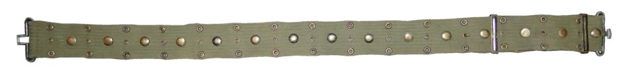
(1) Individual equipment belt (M-67).
(a) Use. The individual equipment belt
(1) helps to support the field pack and carries the entrenching tool and carrier, ammunition pouches, canteen and canteen cover, and first-aid or compass case.
(b) Fitting. The belt is issued in medium and large sizes so that it can be adjusted to fit over all layers of outer clothing, including the complete cold-wet ensemble an the armor vest. If your bare waist measures less than 30 inches, wear the medium size. If your bare waist measures 30 inches or more, wear the large size.
(2) Suspenders.
(a) Use.
Use the suspenders (2) to support the field pack and the equipment belt. The shoulder pads should be centered on your shoulders to distribute the weight of the load evenly. The suspenders may be worn without the field pack. For this wear, attach the suspender straps directly to the equipment belt. Release the front and rear keepers, and position them so that the suspender straps will place the belt evenly at your waist. To keep the weight of the load evenly on both shoulders, attach the rear suspender straps at even spaces from the center of the rear of the belt.
(b) Fitting.
Suspenders are issued in regular, long, and extra-long sizes. If you are under 68 inches tall without shoes, wear the regular size. If you are 68 inches tall without shoes or taller, wear the long size. If you are tall or broad chested and you anticipate wearing the load-carrying equipment over cold-wet outer garments and/or the armor vest, wear the extra-long size. When possible, the size should be determined by the try-on method.
(3) Field pack.
Use the field pack (7) to carry rations and equipment essential for field operations. You can carry certain items in a number of different ways to suit changing conditions.
For example, the poncho can be carried inside the pack under the expandable flap, or it can be attached to the bottom of the pack by means of the two adjustable securing straps. Extra items of small clothing, such as underwear and socks, can be rolled and placed under the expandable flap, as can outer clothing not in use. When you put items in the field pack, place hard items such as ration cans on the outer side and soft items such as clothing on the inner side toward your back. A series of eyelets at the edge of the pack flap will accommodate the double hooks used on old field equipment carriers for such items as wire cutters and machetes.
(4) Entrenching-tool carrier (3). The carrier is designed to carry the collapsible entrenching tool.
(5) Ammunition CMes. Ammunition cases (6) are designed to carry any of the basic loads of ammunition, such as the M-14 and M-16 ammunition.
(6) Canteen cover. Use the canteen cover (4) to carry the canteen and cup. If possible during hot weather, keep the inner lining of the cover wet to help cool the water in the canteen. Keep the cover dry during cold weather because the lining material provides limited protection against freezing of the water in the canteen.
(7) First aid case. Use the first aid case (5) to carry either a field dressing or an unmounted ' magnetic compass.
(8) Sleeping bag carrier. Use the sleeping bag carrier (8) to carry the sleeping bag and other sleeping equipment on your back.
c. Fighting and Existence Loads Concept.
The important point of the fighting and existence loads concept is that the soldier should carry only the items necessary to accomplish his immediate mission. The load the soldier carries should not include any other item that can be provided by an effective and responsive supply system. Because the type of mission, terrain, and environmental conditions will influence clothing and equipment requirements, the unit commander may prescribe the essential items. The prime purpose of the fighting and existence loads concept is to lighten the soldier's load.
(1) Fighting load. The typical fighting load (fig 29) consists of essential items of individual clothing, equipment, weapons, and ammunition which are carried by the foot soldier to accomplish the immediate mission of his unit. See appendix C for a list of typical items included in the fighting load.

Figure 29. Typical fighting load.

Figure 29b. Typical fighting load - continued.

Figure 29a. Typical fighting load - front view.
(2) Existence load. The existence load consists of items other than those in the fighting load which are required to sustain or protect the soldier, which may be necessary for increased personal and environmental protection, and which are not normally carried by the individual. When possible, the existence load items are transported by means other than man-carry. See appendix C for a list of typical items included in the existence load.
d. Assembly for Wearing Pack on Belt. The procedure for assembling the individual load carrying equipment with the field pack on the belt is described below. A different procedure must be followed when the equipment is assembled by parachutists in preparation for a jump. The parachutist's procedure is described in TM 57-220.
(1) Adjust belt. Refer to figure 30, and proceed as follows:
(a) Unfasten the hook on each end of the belt from the center eyelet in which it is engaged, and shorten or lengthen the belt so that it fits around your waist just loose enough not to constrict your clothing.
(b) Fasten the hook for each end of the belt into the nearest center eyelet, and move a sliding keeper close to each hook to prevent the hook from unfastening.

Figure 30. Adjusting individual equipment belt.
(c) Move the other sliding keepers close to the male and female belt fasteners.
(2) Attach field pack to belt. Refer to figure 31, and proceed as follows:
(a) Lay the pack out flat with the back facing up, the flap to the top, and the two attaching clips in an open position.
(b) Lay the belt out flat with the back facing up and the male belt fastener to your left.
(c) Locate the center of the belt, and insert the belt into the two open attaching clips of the pack so that the center of the belt matches the center of the pack.
(d) Close the two attaching clips of the pack, making sure that the tip of the sliding bar engages the hole in the bottom of the clip (see inset).
Note. To avoid losing equipment, fasten all attaching clips properly.
(3) Attach suspenders to field pack and belt. Refer to figures 32 and 33, and proceed as follows:
(a) Lay the suspenders out flat, above the pack, with the inside facing up and the back suspender straps to the bottom.
(b) Attach the back suspender straps to the pack by engaging the hooks' of these two straps into the eyelets of the two webbed tabs of the pack. The open part of each hook should face the back of the pack.
(c) Attach the front suspender straps to the belt by first fastening the belt fasteners.
(d) Fold the suspenders back on the pack so that they lay with the outside of the suspenders facing up.
(e) Engage the hook of the left-front suspender strap into the top eyelet on the front of the belt, nearest the female belt fas ten er ( inset, fig 33); engage the hook of the right-front suspender strap into the top eyelet on the front of the belt, nearest the male belt fastener. The open part of each hook should be to the front of the belt and the loop to the side away from the belt fasteners.
Note. To prevent the equipment belt from "riding up" in front when the ammunition cases are empty or are partially filled, engage the front suspender strap hooks in the top eyelets of the belt at the sides under the arms.
(4) Adjust front suspender straps. Refer to figure 34, and proceed as follows:
(a) Unfasten the belt, put on assembled equipment, and fasten the belt.
(b) Unfasten the buckles on the two front suspender straps.
(c) Center the shoulder pads of the suspenders on the shoulders, and adjust the length of each front suspender strap so that the belt is properly located at the waist.

Figure 31. Attaching field pack to equipment belt and attaching suspenders to field pack.

Figure 32. Attaching field pack to equipment belt and attaching suspenders to field pack.

Figure 33. Attaching suspenders to equipment belt.

Figure 33a. Side view of load bearing gear.
(d) Fasten the buckles to hold the adjustment, pressing each buckle firmly with the thumb to insure that it is fully closed (inset, fig 34).
(5) Adjust back suspender straps. Refer to figure 35, and proceed as follows :
(a) Remove the assembled equipment, and place it on a flat surface with the inner side of pack facing up.
(b) Fasten the belt.
(c) Unfasten the buckles on the two back suspender straps.
(d) Locate the center of each shoulder pad of the suspenders.
(e) Fold the shoulder pads over at the center.
(f) Adjust the length of each back suspender strap so that the belt hangs evenly at front and back.
(g) Fasten the strap buckles to hold the adjustment. Make certain the buckles are properly fastened by pulling slightly on the suspenders.
(6) Attach entrenching-tool carrier to belt. Attach the carrier to the belt on the left side by means of the two attaching clips on the back of the carrier ( fig 36). Do not attempt to insert the clips over two thicknesses of the equipment belt webbing because the clips are designed to accommodate only one thickness of webbing.
(7) Attach canteen cover to belt. Attach the cover to the belt on the right side, next to the pack, by means of the two attaching clips on the back of the cover (fig 36). Note. Although the preferred position for the canteen cover is on the belt as described above, the cover may be attached to the right side of the field pack.
(8) Attach ammunition cases to belt. Refer to figure 36, and proceed as follows:
(a) Attach one case to the belt on the left side, next to the entrenching tool carrier, by means of the two attaching clips on the back of the case.
(b) Unfasten the buckle of the supporting strap of the case.

Figure 34. Adjusting front suspender straps.
(c) Attach the snap of the supporting strap of the case to the metal loop located at the bottom edge of the shoulder pad. Make sure the strap is not twisted.
(d) Adjust the length of the supporting strap so that is has the same amount of strain as the front suspender strap next to it.
(e) Fasten the buckle on the supporting strap to hold the adjustment.
(f) Attach another case to the belt on the right side, next to the canteen cover, using same procedures described above. Note. For carrying a pistol, attach the pistol holster to the belt in place of the ammunition case on the right side of the belt.
(9) Attach first aid case. Attach the case for the first aid packet or lensatic compass in either of the following positions:
(a) To the belt in the front and on the right side next to the ammunition case (fig 36). This is the recommended position.
(b) To the left side of the right ammunition case.
(10) Attach bayonet or bayonet-knife scabbard. Fasten the double hook on the back of the scabbard into the two eyelets of the individual equipment belt or in the eyelets on the field pack flap (fig 36).
(11) Attach hand grenades.
(a) Attach a hand grenade to the side of each ammunition case at the rearmost position so that the grenade is well protected (fig 37). Grenades should be carried in the front on the side of the ammunition case only when the carry of more than two grenades has been authorized.
(b) Slide the safety level of the hand grenade into the loop of the web attachment on the rear of the ammunition case.
(c) Pass the web securing strap on the side of the ammunition case around the top of the hand grenade, and fasten the strap to the glove type fastener on the back of the loop of the web attachment.
(12) Attach sleeping bag carrier to sleeping equipment. To attach the carrier to the sleeping equipment, proceed as follows:

Figure 35. Adjusting back suspender straps.
(a) Lay the carrier out flat with the buckles of the two 1-inch-wide securing straps away from you and with the inside facing up.
(b) Roll the sleeping equipment compactly, and place it on the carrier directly on the top of the carrier handle.
(c) Place the securing straps around the sleeping gear, buckle the straps, and pull the straps tight. Tuck the loose ends of the straps under.
(13) Attach sleeping equipment and carrier to suspenders.
To attach the sleeping equipment and carrier for carry above the field pack (fig 38), proceed as follows: Unfasten the snap fasteners on the two attaching straps of the carrier. Attach the two attaching straps to the suspenders by passing each one through the web keeper on top of the padded portion of the suspenders, through the metal loop located at the bottom edge of the padded portion of the suspenders, back over the top of the web keeper and then fasten the snap fastener of the attaching strap.
Attach the two tie-down straps to the two front suspender straps by passing each one under the supporting straps of the ammunition cases, through the metal loop of the hook on the front suspender strap and then fasten the glove type snap fastener. After assembled load is put on, adjust the length of the two tie-down straps so that sleeping bag will be held firmly in position.

Figure 36. Attaching entrenching tool carrier, canteen cover, ammunition cases, first aid case, and bayonet scabbard to individual equipment belt.

Figure 37. Attaching hand grenades.
e. Assembly for Wearing Pack on Shoulders. The procedure for assembling the individual load-carrying equipment for carrying the field pack on your shoulders is described below. For parachutist's procedure, refer to TM 57-220.
(1) Adjust belt. See d(l) above.
(2) Attach suspenders to belt.
(a) Lay the belt out flat with the back facing up and the male belt fastener to your left, and locate the center eyelet of the belt.
(b) Attach the back suspender straps to the belt, one on each side of the center eyelet, by fastening the hooks on the straps to the top row of eyelets in the belt. Fasten the hooks from the inside to the outside of the belt.
(c) Attach the front suspender straps to the belt by fastening the hooks on the straps to the eyelets nearest the belt fasteners at each end of the belt.
(3) Adjust suspender straps. Put on the assembled belt and suspenders, and adjust the front suspender straps so that the belt is properly located at your waist. Then remove the equipment, and adjust the length of the back suspender straps so that the belt is even in the front and the back.
(4) Attach ammunition cases to belt. See d(8) above.

Figure 38. Sleeping equipment and carrier attached for carry on shoulders above field pack.
(5) Attach first aid case. See d(9) above.
(6) Attach entrenching-tool carrier to belt. See d(6) above.
(7) Attach canteen cover to belt. See d(7) above.
(8) Attach field pack to suspenders.
(a) Attach the two snap hooks on the shoulders at the back of the suspenders into the eyelets of the two web tabs located on the field pack.
(b) Unfasten the two snap hooks of the back suspender straps from the belt eyelets.
(c) Pass the snap hooks and back straps through the two web loops on the field pack, and re-fasten the strap hooks into the belt eyelets.
(9) Attach bayonet or bayonet scabbard. See d(lO) above.
(10) Attach hand grenades. See d(ll) above.
(11) Attach sleeping equipment carrier to sleeping equipment. See d(12) above.
(12) Attach sleeping equipment to pack. If the sleeping equipment roll is small, attach it directly to the bottom of the field pack, with or without the sleeping equipment carrier, by using the pack straps.
f. Carry of Field Protective Mask.
The recommended positions for carrying the field protective mask with the load-carrying equipment are as follows:
(1) The side-carry, with the shoulder strap over the right shoulder, the carrier and mask under the 1eft arm, with the top of the mask placed in the armpit area; and the body strap fastened around the body.
(2) The leg-carry, with the shoulder strap fastened around the waist, and the body strap fastened around the left leg above the knee.
g. Miscellaneous Information.
(1) The individual load-carrying equipment is designed so that it will balance with the equipment belt open. This design makes it possible to obtain ventilation by opening the equipment belt while on the march.
(2) Attaching clips, sliding keepers, hooks, and buckles must be kept free of dirt to insure proper operation of the equipment.
(3) The load-carrying equipment is not fire resistant. It can be quickly damaged by sparks from open fires or by drying it too close to a hot stove. Take special care, therefore, to protect the equipment from sparks and to dry it slowly.
32. Universal Load-Carrying Sling
a. Description.
The universal load-carrying sling (fig 39) is a supplement to the individual load-carrying system for carry of special loads. The adjustable sling is 1 3/4 inches wide and about 6 1/2 feet long. It is provided with lightweight hardware components, such as buckles, slide loops, and V-rings, which can be shifted to the position required to attach various loads capable of being man-carried.

Figure 39. Universal load carrying sling.
b. Use.
Use the sling to man-carry general utility loads, ammunition, and infantry crew served weapon loads in all climates except arctic, where it may have limited use. The sling may be used singly or in combinations of two or more and may be used in conjunction with the individual load-carrying equipment, depending upon the load to be carried. Use should be limited to carry loads of about 35 pounds per sling. Instructions for assembling typical loads to the sling are as follows:

Figure 40. Carrying 3.5 inch rockets.
(1) 3.5-inch rockets. A method for carrying 3.5 inch rockets is illustrated in figure 40. To assemble the load illustrated, refer to figure 41, and proceed as follows:
(a) Adjust the loop end of the sling to the appropriate length for the size and number of rounds of ammunition to be carried (1).
(b) Place the rockets between the slide loops (2).
(c) Adjust the loop end to secure the rockets firmly in place (3).
(d) Attach the adjustable buckle with snap fastener to the V-ring (4).
(e) Adjust the strap to fit the wearer (5). (2) Ammunition boxes. Figure 42 illustrates a method for carrying two boxes of ammunition. For this load, the loop end is adjusted to secure one box, and the adjustable buckle with snap fastener and the V-ring secures the other. (3) Five-gallon water can. Figure 43 illustrates a method for carrying a 5-gallon water can, using two slings.

Figure 41a. Method of assembly for carrying 3.5 inch rockets.

Figure 41b. Method of assembly for carrying 3.5 inch rockets - Continued.

Figure 41c. Method of assembly for carrying 3.5 inch rockets - Continued.
(4) Rations. Figure 44 illustrates a method for carrying a case of rations, using two slings.
(5) Litter. Figure 45 illustrates a method for carrying a litter, using four slings, leaving the carrier's hands free for other use.
c. Practical Application. The load-carrying assemblies described above are typical of the many uses of the sling. Other uses should become apparent to the user under field conditions. The only use restrictions are the stated weight limitations and the design limitation of being used for man-carry purposes only.
33. Pack board
The plywood pack board (fig 46) is an efficient means for carrying large bulky loads. It consists of a rugged frame of molded plywood bent at each side, a canvas backrest fastened to the frame by lacing cords, two pack board attachments, shoulder pads, a lashing rope, and quick release strap and buckle assemblies.
a. Use. Use the pack board to carry loads of considerable weight or of irregular shape. Fifty pounds can be carried easily, and when necessary, more than 100 pounds can be carried. For proper carry of the pack board the pack board canvas backrest should fit against your back, and the pack board frame should support the load.
b. General Instructions.
(1) Before fastening a load to the pack board, make certain the canvas backrest is properly laced to the frame (I below).
(2) Use the pack board attachments to support heavy rigid loads at the bottom. To attach the pack board attachment to the pack board, place the flanges of the attachment over the lower edge of one of the openings in the frame.

Figure 42. Carrying two boxes of ammunition.

Figure 43a. Carrying 5-gallon water can.

Figure 43b. Carrying 5-gallon water can.
(3) Pack all loads so that they will be compact and can be carried high on your shoulders.
(4) Fasten the load to the pack board with a lashing rope or a quick-release strap and clamp assembly. Attach bulky, nonrigid, or irregular shaped loads by means of a lashing rope. Lashing by rope is easier if a short loop is tied in one end of the rope so that it may be attached to a hook on the pack board frame to start the lashing. Always keep the lashing rope attached to the pack board.

Figure 44. Carrying rations.

Figure 45. Carrying a litter.

Figure 46. Plywood pack board.
(5) Keep the lashing simple; never use two loops when one is sufficient.
(6) Use knots that will hold but will not be difficult to untie. When practicable, use a bowline knot to form the loop in the end of the rope.
(7) After lashing, coil the loose end of the rope, and either fasten the coil with a knot or slip the coil between the canvas and the plywood frame.
(8) Keep the lashing rope wound around the top of the pack board when the pack board is not in use.
c. Lashing Loads With Rope.
(1) One method of lashing a load with rope, using four pack board hooks, is described below and illustrated in figure 47.
(a) Form a loop in the rope, and place it over hook AA.
(b) Run the rope across the load to hook A.
(c) Run the rope diagonally downward across the load to hook CC, and back across the load to hook C.
(d) Run the rope back to hook AA as

Figure 47. Diagram showing rope lashing method, using four pack board hooks.

Figure 48. Diagram showing rope lashing method, using six pack board hooks.
shown and then to point K, and secure the rope with a knot at point K.
(e) To tighten the lashing, run the rope from the knot at point K up under point L and back to point K. Tie another knot at point K.
(2) Another method of lashing loads, using six pack board hooks, is described below and illustrated in figure 48.
(a) Make a loop in the rope, and place the loop over hook AA.
(b) Run the rope under hook CC, allowing slack.
(c) Run the rope under hook C, bring it to point M as shown, and pull it through. (d) If an attachment is used (fig 47), tie the rope securely at hook A. If an attachment is not used, run the rope under point P and over to hook AA, and knot the rope.
(3) When a quick lashing is required (fig 49), attach the loop of the rope to hook AA. Hold the rope with your right hand at R and your left hand at L, as indicated in the first step. Then twist your wrist so that the rope appears as indicated in the second step. On the resulting lower loop of the rope, fasten points 1 and 2 to hooks C and CC of the pack board. Tighten the rope and tie it securely at A.
d. Lashing Loads With Quick-Release Strap and Clamp Assemblies. Quick-release strap and clamp assemblies may be used when loads must be packed and unpacked quickly. To do this, place the load on the pack board with the pack board attachment supporting the load at the bottom. Pass the desired number of straps between the pack board frame and canvas and fas ten them around the load ( fig 50). The procedure for tightening a quick-release strap and for closing and releasing a quick-release clamp is illustrated in figure 51.
e. Carrying.
(1) When using shoulder pads, place each shoulder strap through the two loops on the surface of one of the shoulder pads. Adjust the shoulder straps so that the pack board will rest high on your back.
(2) If the pack board is not heavily loaded, sling it on your shoulders as you would any other pack, and adjust the shoulder pads for maximum comfort. If the pack board is heavily loaded, place the loaded pack board upright on the ground, sit with your back against the canvas, and place your arms through the shoulder straps. To mount the load, roll over on your hands and knees, and stand up.

Figure 49. Diagram showing quick lashing method.

Figure 50. Diagram showing load fastened to pack board with quick-release strap and clamp assemblies.

Figure 51a. Procedure for fastening and releasing pack board with quick-release strap and clamp assemblies.

Figure 51b. Procedure for fastening and releasing pack board with quick-release strap and clamp assemblies - continued.
(3) When desirable, attach the pack board to your waist by passing a spare quick-release strap and clamp assembly through the bottom holes on each side of the pack board frame and fastening the buckle at the front of your body.
f. Lacing Canvas Backrest to Frame.
(1) Tie the end of a lacing cord into the top eyelet on one side of the canvas. Hold the canvas so that its edge is about 11/ 4 inches from the pack board frame, and run the cord around the edge of the pack board frame and twice through the top hole of the frame. Run the cord down along the inside of the frame, through the second hole of the frame, around the edge of the frame, through the second eyelet of the canvas, around the edge of the frame, and again through the second hole of the frame. Repeat the procedure until the cord reaches the bottom hole of the frame on one side. Run the cord twice through the bottom hole of the frame and around th.e edge of the frame, and tie the cord to the bottom eyelet of the canvas. Be sure the edge of the canvas is about 1 1/ 4 inches from the frame all along the side of the pack board.
(2) Follow the above procedure to lace and tie the other edge of the canvas to the opposite side of the pack board frame.
(3) Tighten the lacings on the canvas before packing a load, and re-tighten them as often a necessary to keep the canvas taut. To tighten lacings, twist the cord around a stick and pull the cord tight. Lacings may also be tightened by placing the pack board frame on edge, gradually applying gentle pressure until the frame is slightly bowed, and then tightening the lacings. When the pressure is released, the frame will return to its original shape and tauten the canvas.
g. Care.
Mend or repair damaged fabric components before the damage becomes serious. When fabric becomes soiled, wash and sun it; when necessary, scrape off caked mud. The canvas backrest will need more frequent washing and sunning than the shoulder straps. If the hooks on the frame become loose, tighten them. Make certain that the lacings that fasten the canvas backrest to the frame are taut enough to prevent the frame from pressing against your back; a taut canvas also allows air to circulate between the frame and your back. Do not drop the pack board; lay it down gently.
34. Mission Loads.
At times it is necessary for you to adjust basic loads and load-carrying equipment to compensate for the carry of equipment and supplies required to fulfill your unit mission or to suit your particular assignment. These mission loads are carried by using certain combinations of the lightweight load-carrying equipment (para 31), the universal load-carrying sling (para 32), the plywood pack board (para 33), the grenade carrier vest (para 36), and the various bags (para 37). Typical mission loads, using combinations of the individual load-carrying equipment and the universal load carrying sling, are depicted in figure 52.
35. Lightweight Rucksack
a. Description. The lightweight rucksack, with riveted frame (fig 53), weighs about 3 1/2 pounds and consists of: a tubular frame to which all other components are attached, straps (including shoulder straps, cargo straps, back straps, and a waist strap), a combat pack, a rifle carrier consisting of a detachable rifle butt pocket and a detachable rifle strap, and a camouflage cover. A cargo support shelf is issued on an optional basis.
b. Location of Assembly Instructions.
Complete instructions for assembling the lightweight rucksack are detailed on the instruction sheet which is packed with each rucksack. This instruction sheet is located in the pouch flap pocket.
c. Wear. Wear the rucksack.
with any type of load attached, so that the lower back strap is positioned to fit on you comfortably. Adjust the waist strap by shortening or lengthening it so that it fits around your waist just tight enough so as not to constrict your clothing. Adjust the shoulder straps so that the lower backs trap fits comfortably.

Figure 52. Typical mission loads using individual load-carrying equipment and load-carrying sling.
d. Placement of Loads.
(1) Combat pack.
Place heavy objects near the frame, and sharp objects near the center so they will not rub against the bag. Use the side pockets for frequently needed items. Use side web hangers for attaching canteen(s). Use the flap pocket for storing items such as maps and the camouflage cover.
(2) Sleeping equipment.
Roll the sleeping equipment, including the poncho, and secure it above the combat pack by using the cargo straps.
(3) Upper storage bag.
Use a waterproof bag when additional storage capability is required for loose items, sleeping equipment, and special mission equipment and supplies. Arrange items in the bag in such a way as to protect sensitive items from damage after the bag is positioned above the combat pack and secured to the frame by the cargo straps. Wrap heavy items in the sleeping gear or extra clothing. Center the bag above the combat pack to provide a well balanced load, and prevent damage to the rucksack or injury or discomfort to the wearer. This provides

Figure 53. Lightweight rucksack.
additional capacity to meet requirements and provides a built-in cache capability. Remove the bag from the frame by loosening the cargo straps and readily disposing of it if the situation so requires.
e. Conversion to a Pack board.
(1) Remove the combat pack from the rucksack frame. Remove the cargo straps from the middle horizontal bar of the frame and attach them to the bottom horizontal bar of the frame.
(2) From outside of the frame, insert the right metal attachment tab of the cargo support shelf above the bottom horizontal bar and behind the right vertical bar of the frame. Insert the left metal attachment tab behind the left vertical bar in the same manner so that the shelf rests on the bottom horizontal bar of the frame.
(3) From the underside of the cargo support shelf, lace left and right cargo straps through the slots in the cargo support shelf.
(4) Place the load on the cargo support shelf, wrap the cargo straps around the load, and secure the straps to the buckles at top of the frame.
f. Conversion to Combination Pack board and Combat Pack. Attach the cargo support shelf to the rucksack frame above the middle horizontal bar and combat pack in the manner described in e above. Insert the cargo straps through the slots in the cargo support shelf as described in (e) above.
g. Adjustment for Firing Position. To adjust the rucksack so that it will not interfere with the firing of infantry weapons while the wearer is in the prone position, proceed as follows:
(1) For Right-handed persons. Grasp the thong on the right shoulder strap lower adjusting buckle and pull forward and upward to release strap adjustment Shift rucksack toward left shoulder and assume prone firing position.
(2) For Left-handed persons. Loosen the left shoulder strap. Shift rucksack toward the right shoulder and assume a prone firing position.
h. Emergency Quick Release.
In emergency situations when quick removal of the rucksack is required, unsnap waist strap fastener. Grasp the quick release snap fastener tape on the left shoulder strap. Pull down on the quick release fastener tape, shift the rucksack toward the right shoulder and let it drop.
i. Care.
Clean the rucksack frame by washing it with a damp cloth. Rinse it and dry it thoroughly. Do not sit or jump on the frame. Clean the fabric components by washing them in a warm solution of mild soap or detergent. Rinse them with clean water, and dry them thoroughly in the shade or indoors.
36. Grenade-Carrier Vest.
The M-79 grenade-carrier vest (fig 54) is designed to be worn over the armor vest and the suspenders of the individual load-carrying equipment. It enables the wearer to carry twenty 40-mm. grenades for the M79 and M203 grenade launchers, and four 40-mm. pyrotechnic cartridges. Each grenade is held in place in the pocket by a snap fastener closure; each grenade can be removed with one hand. If your chest measures 38 inches or less, wear the small size; if it measures from 39 to 42 inches, wear the medium size; and if it measures 43 inches or more, wear the large size.
37. Bags (fig 55)
a. Barrack Bag.
The olive drab barrack bag (A) is used for general storing and carrying purposes. Close the bag with the drawstrings.
b. Clothing Bag.
The waterproof clothing bag (B) is used for carrying rations, extra clothing, and personal effects that must be protected from moisture, especially during amphibious or jungle operations. It is not constructed to withstand rough use or handling. The bag is also used to carry and store the sleeping bag and blanket. Close the bag by tying the tie cord around the mouth of the bag.
c. Duffel bag.
The duffel bag (C), with handle and shoulder straps, is used in the field for carrying your individual clothing and equipment not carried in the field pack or by you. Close the duffel bag by folding the top of the bag in envelope fashion, placing the grommets over the U-shaped keeper, and attaching the snap on the carrying strap to the keeper. Carry the bag by the handle as a suitcase, or by the shoulder straps slung over your shoulder pack-style.
d. Waterproof Covers.
(1) Description and use.
The multipurpose waterproof covers are plastic (polyethylene) bags used to provide lightweight, waterproof protection for small arms against rain and moisture. The dimensions and uses of the covers are shown in table 4.
Table 4. Multipurpose, waterproof covers.
| Size Designation | Dimensions (inches) | Use |
| 1 | 8 by 18 | For pistol or personal effects. |
| 2 | 10 by 56 | For rifle or carbine |
| 3 | 15 by 45 | For submachine gun |
| 4 | 20 by 84 | For machine guns |
(2) Additional uses. The multipurpose waterproof covers may also be used for-

Figure 54. Grenade-carrier vest.

Figure 54a. Grenade-carrier vest - back view.

Figure . Grenade vest.
(a) Carrying water.
(b) Protecting miscellaneous small items of clothing and equipment.
(c) Improvising facilities (inflated covers) for lightweight water-crossing operations.
(d) Lining the duffel bag to form an emergency waterproof clothing bag. For this purpose, the size 3 cover (table 4) is used. About 21 inches should be cut off the top of the cover to make it a suitable length before it is inserted into the duffel bag.

Figure 55. Barracks, clothing, and duffel bags.

Figure 55c. Barracks, clothing, and duffel bags - continue.
38. Identification (ID) Tags and Necklace.
Wear your identification tags at all times when in the field, when engaged in field training, when traveling in aircraft, and when outside the continental United States. One tag is suspended from the neck underneath the clothing by a 25-inch, noncorrosive, nontoxic, heat-resistant material, looped to form a necklace. A second tag is fastened to the necklace below the first tag by a 2 1/2 inch extension of material similar to that of the necklace.
39. First Aid Packet
The first aid packet is a sealed box containing sterilized cotton gauze which is used for emergency dressing of wounds when medical services are not immediately available. Do not open the packet until needed; exposure to air may cause the contents to become soiled and non sterile.
40. Compass
The magnetic lensatic compass is used to establish direction. An accurate line of direction can be established for a specific object by using the arrangement of a lensatic eye lens, a reticular sight line, and the object being sighted. When you are not using the compass, keep it in its case to protect it from dirt and dust.
41. Waterproof Matchbox.
The waterproof matchbox (fig 56) provides a means for keeping matches dry and for starting fires by spark ignition for emergency purposes. The box is a small, cylindrical, plastic container with a screw cap, a striking disk, and a striking bar. A sealing gasket fits inside the screw cap and provides a tight seal when the cap is screwed finger tight onto the cylinder. The striking disk, which is mounted on the inside top surface of the cap, has an abrasive surface for striking safety matches. The striJcing bar, located on the bottom of the container, is made of a material that produces a spark when it is struck with the sharp edge of a knife or other metallic object.
42. Field Protective Mask (M-17A1)
The field protective mask includes the mask, the carrier, and two lens outserts. The mask protects the wearer's face, eyes, and respiratory tract against field concentrations of chemical biological (CB) agents, in the form of gases or aerosols, and protects the face and eyes against contamination from splashes and liquid droplets of the agents. Detailed information on the care and use of the field protective mask is covered in FM 21-40 and TM 10-277.

Figure 56a. Waterproof matchbox - Side View

Figure 56b. Waterproof matchbox - continued.
43. Entrenching Tool
a. Description.
The collapsible entrenching tool (fig 57) is about 9 1/ 2 inches long when collapsed and about 23 1/2 inches long when fully extended. It has a hollow triangular-shaped handle. One edge of the blade is sharpened for cutting; the opposite edge is serrated to aid in digging, in addition to serving as a chopping device. The blade can be adjusted into appropriate positions by loosening the locking nut at the blade end of the handle, adjusting the blade to the desired position, and tightening the locking nut.
b. Use.
Use the entrenching tool for digging, breaking hard ground, clearing brush or undergrowth, and cutting roots, saplings, and small trees. Do not use the tool for cutting large-size timber.
(1) Shoveling or cutting.
Extend the shovel blade outward in a straight-line projection of the handle.
(2) Clearing ground.
Turn the shovel blade to a position perpendicular to the handle.
c. Care.
Clean the entrenching tool after each use. Keep the threads on the locking nut oiled to insure ease of operation. Take care not to subject the tool to misuse or undue strain.
44. Bag and Case Carrying Sling.
The bag and case carrying sling is an auxiliary sling used to carry the field pack when the field pack suspenders are not required.
45. Canvas Cot and Insect-Bar Frame.
The collapsible canvas cot has three sets of folding legs. The insect-bar frame is made of wood and consists of four upright members which are fitted to the bottom of the end cot legs by means of steel clips ( fig 58). Two crosspieces serve as braces for the uprights. Use of the insect-bar frame with the canvas cot is described in paragraph 46b (2).
46. Insect Bar.
a. Description.
The field-type insect bar is a canopy made from netting of small nylon mesh.

Figure 57. Collapsible entrenching tool.

Figure 58. Canvas cot and insect-bar frame.
b. Use.
Use the field-type insect bar for protection against mosquitoes, sand flies, and other small insects.
(1) Fastening bar inside shelter-half tent. The insect bar may be fastened inside the shelter-half tent while the tent is being pitched (fig 59).
(a) Snap fasten the shelter halves together, and place them over the spread-out insect bar so that the foot stops of the tent are aligned with the tie tapes near the bottom edges of the insect bar, and the grommets at the ridge of the tent are aligned with the slits at the top of the insect bar.

Figure 59. Using field-type insect-bar with shelter-half tent.
(b) Place the tent pole spindles through the slots at the top of te insect bar and through the grommets at the ridge of the tent.
(c) Continue pitching the tent as described in paragraph 25a( 1) and as shown in figure 22.
(d) After folding the end sections of tent over the sides of the tent, tie the tapes near the bottom edges of the insect bar around the tent pins.
(2) Suspending bar over cot or bed. The insect bar may be suspended over a folding canvas cot or metal bed.
(a) When used with a canvas cot, attach a wooden insect bar frame (para 45) to each end of the cot, and tie the tie tapes to the top corners of each frame.
(b) When used with a metal bed, attach a T-shaped metal frame to each end of the bed, and tie the tie tapes at the top corners of the insect bar to the ends of the crosspieces at the top of each T-shaped frame.
(3) Suspending bar from trees or bushes. For protection outdoors when a tent is not available, suspend the insect bar by tying the tie tapes at the top corners to trees or bushes.
c. Packing.
Fold the insect bar into a small bundle, and either place it in the field pack or attach it to the pack. It also may be placed in the duffel bag.
47. Hat and Mosquito Net.
Wear the hat and mosquito net for protection against mosquitoes and other insects (fig 60). The cloth top piece has an elastic suspension that fits over the head or helmet. It may also be worn between the liner and the helmet. Metal rings hold the net away from the face and neck even when the wearer is sleeping. The hat and mosquito net fits over the collar in back and is held in place in front by two elastic loops that can be attached to the pocket buttons of the shirt. An elastic draw tape at the bottom may be drawn tight when the net is not fastened to the pocket buttons.
48. Multipurpose Net.
The nylon multipurpose net (fig 61) is about 5 feet wide by 9 feet long. Two cords, about 14 feet long, are included with each net. When folded, the net can be attached to the individual equipment belt in a manner similar to that described for the poncho (para 23), or it can be attached to the rucksack harness (para 35). The net is usable as a hammock, a camouflage net, a carrier for bulky loads, a litter, a seine for fishing, a trap for catching game, a cache for food or ammunition, a

Figure 60. Wearing hat and insect net over helmet.

Figure 61. Multipurpose net.
Sniper's roost, and many other field expedients. TM 10-276 provides detailed information on the multipurpose net.
49. Knitted Wool Scarf
The knitted wool scarf is a tubular seamless type with reinforced ends. In addition to being used for warmth around the neck, the scarf, in emergencies, may be folded one and a half times and used as a cap or may be folded twice and used as a hand muff.