THE AN-M3 .50 CALIBER MACHINEGUN - FIELD MAINTENANCE INSTRUCTIONS.
| CHAPTER 4 - FIELD MAINTENANCE INSTRUCTIONS | |||
| Section | I | General maintenance | 81,82 |
| II | Parts, special tools, and equipment for field maintenance | 83-87 | |
| III | Inspections | 88,89 | |
| IV | backplate assembly | 90-93 | |
| V | Bolt group | 94-97 | |
| VI | Barrel buffer group | 98-101 | |
| VII | Barrel and barrel extension group | 102-105 | |
| VIII | Cover group | 106-109 | |
| IX | Receiver and barrel jacket group | 110-113 | |
| X | Final inspection and return to ordnance for rebuild | 114-117 |
1. Scope
a. This manual is published for the information and guidance of personnel to whom this materiel is issued and also personnel responsible for performing field maintenance. It contains information on operation, organizational and field maintenance as well as ammunition, shipment and limited storage, and destruction of materiel to prevent enemy use. It also contains description of major units and their function in relation to other components of the materiel. It applies only to the cal. .50 basic aircraft machinegun AN-M3 (figs. 1 and 2),
b. The publication of these field maintenance instructions is not to be construed as authority for the performance by organizational maintenance personnel of those functions that have been restricted to field maintenance shops. In general, the prescribed maintenance responsibilities will apply as reflected in the allocation of maintenance parts listed in ORD 7 SNL A-67 and in the appropriate columns of the ORD 8 SNL A-67 supply manuals. Instructions for field maintenance are to be used by organizational maintenance personnel only when the tactica1 situation makes the repair function imperative.
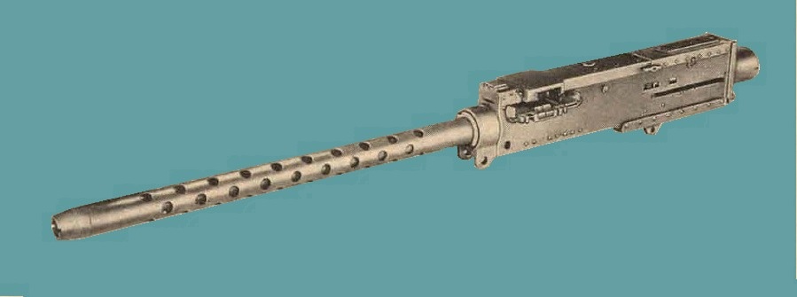
Figure 1. Cal. .50 basic aircraft machinegun AN-M3 - Left side view.
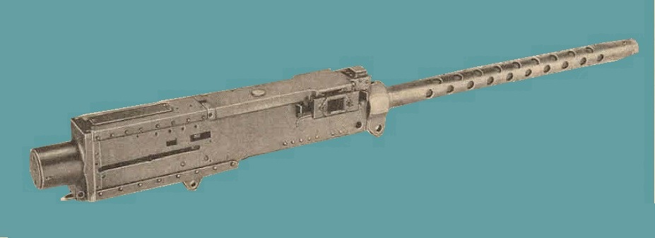
Figure 2. Cal. .50 basic aircraft machinegun AN-M3 - Right side view.
a. The appendix contains a list of current references, including supply and technical manuals, and other available publications applicable to the materiel.
b. Authorized Forms. The forms generally applicable. to using organizations are listed in the appendix. For a current and complete listing of all forms (as of 1968), see DA Pam 310-2 or AFR 9-2. For instructions on use of these forms, see FM 9-10.
c. Field Reports of Accidents.
(1) Injury to personnel or damage to materiel.
The reports necessary to comply with the requirementH of the Army safety program are prescribed in detail in SR 385-10-40 and AFR 136-9. These reports are required whenever accidents involving injury to personnel or damage to materiel occur.
(2) Ammunition.
"Whenever an accident or malfu,nction involving the use of ammunition occurs, the incident will be reported by ordnance personnel as prescribed in SR 700-45-6 and by Air Force personnel as prescribed in SR 385-310-1/ AFR 50-13 by the officer under whose supervision the ammunition is maintained or issued.
d. Unsatisfactory Report.
Reports of accidents or suggestions for improvement in manufacture, design, maintenance, safety, and efficiency of operation or malfunction of the weapon, spare parts, or equipment should be reported in accordance with AF Form 54 or DA Form 468 (Unsatisfactory equipment Report) with all pertinent information necessary to initiate corrective action. This form also will be used for reporting complaints on the application or effect of prescribed lubricants and preserving materials and when so used will contain identifying details on both the products and the associated equipment.
e. Air Force Fonn 185. TO 00-35D-185 establishes and prescribes the use of AF Form 185 (Maintenance and Performance Report, Aircraft Automatic Gun) which is to be used by all Air Force activities storing, issuing, operating, or maintaining aircraft guns. AF Form 185 will remain with the, guns until the guns to which they pertain are disposed of by the Air Force .
2. Forms, Records, and Reports
a. General. Responsibility for the proper execution of forms, records, and reports rests upon the officers of all units maintaining this equipment. However, the value of accurate records must be fully appreciated by a.11 persons responsible for their compilation, maintenll,nce, and use. Records, reports, and authorized forms are normally utilized to indicate the type, quantity, and condition of materiel to be inspected, to be repaired, or to be used in repair. Properly executed forms convey authorization and serve as records for repair or replacement of materiel in the hands of troops and for delivery of materiel requiring further repair to ordnance shops in arsenals, depots, etc. The forms, records, and reports establish the work required, the progress of the work within the shops, and the status of the materiel upon completion of its repair.
3. Description
a. The caL .50 basic aircraft machinegun AN-M3 is an automatic recoil-operated, link-belt-fed, air-cooled machinegun; having a rate of fire over 1,000 rounds per minute. A metallic-link belt of the disintegrating type is used to hold the ammunition until it is fed into the gun. Depending upon the positioning of some of the component parts, ammunition can be fed from either the left or right side of the gun. The relationship of groups and assemblies of the cal. .50 basic aircrdt machinegun AN-M3 is shown in figure 3.
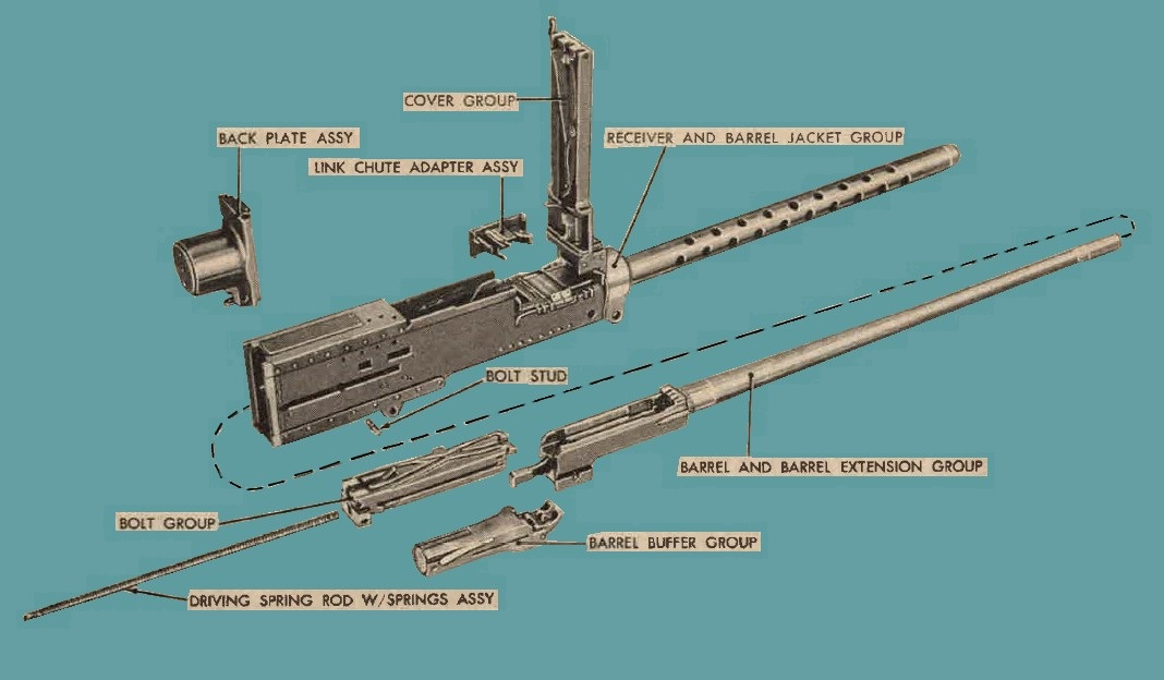
Figure 3. Relationship of groups and assemblies for cal. .50 basic aircraft machinegun AN-M3.
b. The gun can be mounted in the wing or fuselage 0£ a fighter plane or it can be mounted in bomber turrets. c. The gun fires percussion-type primed ammunition and is fired by an electrcnically operated solenoid. The solenoid may be mounted on the top plate or on either side of the gun, depending upon the positioning of certain component parts.
4. Serial Number Information
a. One serial number is required for records concerning this gun. The serial number (fig. 4) is located on the right side plate just below the feed way and on the top plate ( fig. 5).
b. The number of the trunnion block shim (fig. 4), which denotes its thickness, is trunpad on the right side plate and on the right side of the trunnion adapter and is the shim that is required for proper assembly of the gun at manufacture.
5. Tabulated Data
Data pertaining to cal. .50 basic airqraft machinegun AN-M3 are tabulated in a and b below.
a. General.
| NUM | ITEM | CHARACTERISTICS | |
| 1 | Weight of gun without recoil adapter | 64 1/2 lbs | |
| 2 | Weight of recoll adapter assembly | 4 1/2 lbs | |
| 3 | Weight of barrel | 10.91 lbs | |
| 4 | Length overall | 4 feet 9 1/2 inches | |
| |
|||
| 5 | Rifling | ||
| 6 | Length | 34 9/64 inches | |
| 7 | Number of grooves | 8 | |
| 8 | Twist (direction) | Right-hand | |
| 9 | Twist (one turn-in) | 15 in. | |
| 10 | Operation | short recoil | |
| 11 | Feed | link belt | |
| |
|||
| 12 | Firing pin release : | ||
| 13 | Pressure applied to sear slide | 38 lb (max) | |
| 14 | Pressure applied to sear | 26 lb (max) | |
| 15 | Belt pull 1 | 35 lb | |
| 16 | Cooling | Air | |
| |
b. Performance.
| NUM | ITEM | CHARACTERISTICS |
| 1 | Rate of fire | 1,150 to 1,250 Rds per minute |
| 2 | Maximum number of rounds that can be fired in one burst without danger of overheating | 200 Rounds |
| 3 | Service life of gun | 15,000 Rounds |
| 4 | Muzzle velocity | 2,730 TO 3,450 FPS |
| 5 | Range | 5,350 to 7,275 yrds |
1. The "belt pull" indicates the belt load that can be imposed on the gun-without causing malfunctions under standard test conditions (par. 116).
2. See cook-off and barrel life data in paragraph 19.
3. Service life indicate the approxtmate number of rounds that may be fired, after which the weapon must be turned in for rebuild.
4. Muzzle velocity and range depend upon type of ammunition fired. See paragraph 122.

Figure 4. Location of serial and trunnion block shim numbers.
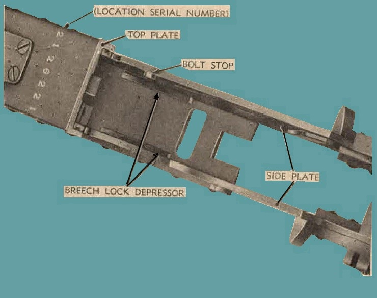
Figure 5. Location of serial number on top plate.
Note. Controls and sights used for firing this gun are furnished by the air force and are covered in pertinent Air Force techniv=cal orders.
6. General a. When new or reconditioned materiel is first received by the using organization, it is necessary for the organizational mecbanic to determine whether the materiel is complete and has been proper1y prepared for service by the supplying organization. For this purpose, inspect nll assemblies, subassemblies and accesories to be sure they are properly assembled, secured, clean and correctly adjusted or lubricated. Reference to paragraphs 51 thruogh 80 will provide information on components 0f the various major groups 0f the gun.
b. A record should be made 0f any missing parts and 0f any malfunctions. Any such conditions should be corrected as quickly as possible.
c. Attention should be given to small and minor parts, as these are more likely to become lost and may seriously affect proper functioning of the machinegun.
d. The materiel should be cleaned and prepared for service in accordance with instructions given in paragraphs 7 and 8.
7. New Materiel
a. New machineguns received from storage are packed in a heat sealed, water-vaporproo£ barrier bag lined with volatile corrosion inhibitor material (VCI) . Guns previously were packed in water-vaporproo£ bags and cotton stockinettes (Saran packing).
b. Guns packed using these methods are completely coated with a light film of special preservative lubricating oil and are serviced as described in (1) through (5) below.
(1) Remove gun in cradle from the shipping container by removing sight screws from the removable end 0f box.
(2) Remove wooden cradle used to support the gun in the container by removing two screws from end near backplate assembly.
(3) Remove speed nuts by bending outward with a screwdriver. Slide pins out of weapon and remove barrier bag by cutting off the sealed end.
(4) Remove backplate assembly (par. 52) and withdraw wooden block from the receiver. Remove VCI tube from bore of barrel.
(5) The gun is now ready for use. However, to insure that there is no corrosion present, missing parts, or incorrect assembly, proceed as outlined in (a) through (l) below.
(a) Disassemble the gun to the extent outlined in paragraph 9.
(b) Clean film of oil from all parts. Check front face of bolt and other surfaces subjected to powder fouling for corrosion. Check parts for cracks and other visual defects.
Note. It will be noticed that some of the internal moving parts will show what appears to be slight wear. Each new machinegun is test-fired a minimum of 200 rounds, which wears away portions of the protective finish applied to component parts. This is a normal condition and is not to be construed as excessive wear.
(c) Clean bore, using cal. .50 jointed cleaning rod M7-6535441 (fig. 16) and patches.
(d) Clean chamber, using the chamber cleaning brush M6- 6108828 (fig. 15).
(e) Check materiel to make sure that all technical orders have been applied. Current teclmical orders are indexed numerically and alphabetically in TO 00-1-39.
(f) Lubricate materiel as outlined in paragraphs 33 and 34 and assemble gun.
(g) Check head space and adjust if necessary (par. 14).
(h) Check timing and adjust if necessary (par. 15).
(i) Check backplate adjusting screw for proper adjustment (par. 54d).
(j) Check Air Force technical orders for any special equipment used with this materiel that is the responsibility of the Air Force. Different types of aircraft use various types of equipment.
(k) Check spare parts and equipment with Department of the Army Supply Manual ORD 7 SNL A-67.
(l) Inspect special tools and equipment listed in paragraphs 27 through 32.
8. Used Materiel.
Used materiel requires the same inspection and service as prescribed for new materiel (paragraph. 7) and, in addition, the checks outlined in a and b below.
a. Check all components of the materiel for signs of excessive wear, damage, missing parts, or coITosion and correct any deficiencies.
b. Check AF Form 185 for the number of rounds fired and perform the 5,000- or 10,000-round inspection (par. 37b (3) and (4)) if necessary. Guns that have fired more than 15,000 rounds must be returned to the Ordnance Corps for rebuild.
9. Disassembly of Gun Prior to Cleaning
Remove and disassemble the groups indicated below:
a. Cover group (par. 74).
b. Backplate ::tssembly (par. 52).
o. Driving spring rod with springs assembly and bolt group (pars. 56 and 57).
d. Barrel buffer group (pars. 62 and 63).
e. Barrel and barrel extension group (pars. 68 and 69).
f. Receiver and barrel jacket group (par. 78).
Note. Barrel jacket ancl trunnion adapter or recoil adapter assembly need not be disassembled.
10. Cleaning Guns and Components Coated With Rust-Preventive Compound.
a. Vapor degreasing should be used to remove compound if available. A brusli saturated with dry-cleaning solvent or volatile mineral spirits or a solution of four parts dry-cleaning solvent or volatile mineral spirits and one part grease-cleaning compound may be used. After cleaning materiel, dry with a lint-free wiping cloth and lubricate the gun as outlined in paragraphs 33 and 34.
b. Component parts of each gun should be cleaned separately. Although like parts are interchangeable, the parts originally assembled to the gun work best together.
c. Wherever the rust-preventive compound can accumulate, particular attention should be given to remove all of the compound. This situation applies especially to the bolt group. The firing pin tunnel in the bolt should be cleaned, using the cal. .50 firing pin hole cleaning brush 7162702 and cleaning patch end 7162704 (fig. 15) with patches. The cal. .45 cleaning rod M4-5564102 (fig. 16) is used in conjunction with the brush and encl. The hole in the bolt £or the driving spring rod with springs assembly should also be thoroughly cleaned. The firing pin extension assembly should be disassembled (par. 57k) in order to remove compound from spring inside the extension.
11. Cleaning Guns in Use.
a. Rifle-bore cleaner is used £or cleaning the machinegun after it has been fired or £or periodic cleaning as outlined in paragraph 39.
b. Rifle-bore cleaner contains a volatile solvent that evaporates at temperatures above 150° F., thus reducing the cleaning action. Therefore, after firing, the weapon should not be cleaned until it has cooled to the point where the barrel can be touched with bare hand. Note. Rifle-bore cleaner will not be diluted.
12. General
This section contains instructions for the steps necessary to operate the gun under onditions of moderate temperatures and hunidity. For aicraft guns, usual operating conditions are considered the atmospheric conditions ordinarily encountered while flying at low altitudes in a temperature zone. For operation under unusual conditions, see paragrnphs 21. Throucrh 26.
13. Installation of Gun in Aircraft
MachineGun installation in aircraft is the reSpOnsability of the Air Force. Instructions for mounting the gun in aircraft are covered in Air Force technical orders.
14. Checking and Adjusting Head Space.
a. General. Head space is the distance between the front face of bolt and the rear end of barrel. Head space is correct when this distance is bet"·een 0.202 and 0.206 inch. Proper head space adjustment permits the breech lock to ride smoothly up the breech lock cam into fully locked position, making positive contact with the forward wall of the breech lock recess in the bolt. Improper adjustment of head space will cause malfunctions and possible damage to gun. Head space must be checked and adjusted each time the gun is assembled und at any time correctness is doubted. Malfunctions due to improper head space adjustment are listed in band b below.
b. Tight Head Space. Tight head space may cause the malfunctions listed in (1) through (3) below.
(1) Failing of the recoiling parts to go completely into battery because the breech lock cannot fully enter the locking recess in the bolt.
(2) Failme of gun to fire because the bolt cannot travel forward enough for the sear to be depressed.
(3) Sluggish fire because of binding and excessive friction of moving parts (particularly noticeable when pulling a long ammunition belt).
c. Loose Head S pace. Loose head space may cause the malfunctions listed in (1) through (3) below.
(l) Rupturing of the cartridge case because the bolt cannot hold the cartridge snugly in the chamber.
(2) Inability to obtain proper timing.
(3) Battering of the breech lock, bolt, and barrel extension because the locking surfaces of the breech lock are not in positive contact with the bolt recess at instant of firing.
d. Adjusting Head Space Without Gage.
(1) To adjust head space without gage, pull the bolt back about three-quarters of an inch by means of the bolt handle or other retracting device.
(2) Screw the barrel into the barrel extension (fig. 6), by engaging the barrel notches with a screw driver, until the recoiling parts will not go into battery position (do not force) when the bolt is released. In battery position, the barrel extension touches the trunnion block.
Note. For ease in turning the barrel into the barrel extension, remove the link chute adapter assembly.
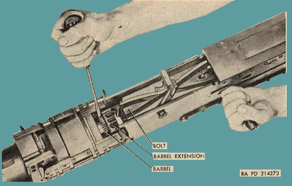
Figure 6. Turning barrel into barrel extension with link chute adapter assembly removed.
(3) Screw the barrel out of the barrel extension, one notch at a time, until the recoiling parts will just go into battery position under pressure of the driving spring when the bolt is released.
Note. Do not retract the bolt more than three-quarters of an inch when determining the point at which the recoiling parts will just go into battery without being forced.
(4) Retract the recoiling parts as in (1) above and unscrew the barrel an additional two notches to allow for expansion.
e. Checking Head Space with Oal. .50 Head Space and Timing Gage 5351217. Head space gage 5351211 (GO and NO GO) is used to check the head space of cal. .50 machineguns. This gage is part 0f the cal. .50 head space and timing gage 5351217 (fig. 7). To check head space, proceed as described in (1) through (3) below.
(1) Retract the recoiling parts fully and allow them to return to battery position in order to cock the firing pin.
(2) Retract the bolt until the barrel extension is approximately one-sixteenth of an inch from the trunnion block. This operation foeces the contacting surface of the breech 1ock and breech lock recess of the bolt together. This is the position of the recoiling parts when a round is chambered and ready to be fired.
(3) Attempt to insert the GO and NO GO ends of the gage in the T-slot between the front face of the bolt and rea.r of the
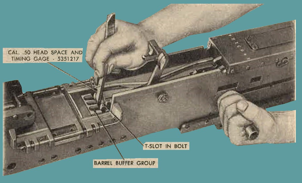
Figure 7. Using Cal. .50 head space and timning gage 5351217 to check head space (link chute adapter assembly removed to show operation.)
barrel. If the GO end does not enter the T-slot, the head space is too tight; if the NO GO encl enters the T-slot, the head space is too loose.
Note. The head space from one side of the T-slot to the other side will vary and, on some weapons, to the extent that one side will always be out of adjustment. It is recommended, therefo1·e, that head space be measured from the center of the T-slot.
(a) Loose head space. If the head space is found to be loose, correct the adjustment by screwing the barrel into the barrel extension (fig. 6), one notch at a time, checking with the NO GO end of gage until the NO GO end of the gage will not enter. Attempt to insert the GO end of the gage, and if it enters, the head space is correct.
(b) Tight head space. If the head space is found to be tight, correct the adjustment by unscrewing the barrel, one notch at a time, checking with the GO end of the gage each time until the gage enters. If the GO end of the gage enters and the NO GO end of the gage will not, the head space is correct.
(4) Remove gage and release firing pin. Caution: Never release the firing pin with the gage in place, as this will damage the firing pin.
Note. The gage may be inserted from either the top or bottom of the gun. In the event the gage is inserted from the bottom, the locking surface of the breech lock and bolt may be fully engaged by inserting a screwdriver between the bolt and the end of the barrel and prying the bolt back.
15. Checking and Adiusting Timing
a. General.
The procedure of adjusting the weapon to fire at the correct point during its operating cycle is known as "timing." A correctly timed gun fires just before the barrel extension strikes the trunnion block on the receiver, thus cushioning the impact. The gun can be incorrectly adjusted to fire either "early" or "late," releasing the firing pin too soon or too late. In extreme cases of early timing, the gun will fire two rounds and then stop because recoil from the second round started before the extractor was far enough forward to engage the next round in the belt. In late timing, the barrel extension will strike the trunnion block too hard when the recoiling parts move forward during counterrecoil. The gun should be timed to fire when the space between the barrel extension and the trunnion block is from 0.020 inch to 0.116 inch as determined with cal. .50 head space and timing gage 5351217 (fig. 8).
b. When to check Timing. Timing should be checked at regular intervals, since the adjustment may be disturbed as a result of vibration, worn parts, and disassembly or replacement of parts. Timing should always be checked whenever head space is checked or a new solenoid installed. See applicable Air Force technical orders for trigger bar adjustable stop and top and side plate solenoid adjustments.
c. Checking Timing to Insure That Gun Will Not Fire Too Late.
(1) Check head space (par. 14).
(2) Cock the gun fully by retracting the recoiling parts and allowing them to go forward into battery.
(3) Raise the cover and retract the bolt about one-quarter of an inch.
(4) Insert the FIRE ( 0.020 in) leaf of the cal. .50 head space and timing gage 5351217 (fig. 8) between the barrel extension and trunnion block.
(5) Allow the barrel extension to close slowly on gage.
(6) Attempt to release the firing pin by energizing the solenoid. The firing pin should release smartly. If the firing pin is not released, the trigger bar adjustable stop and/or the solenoid
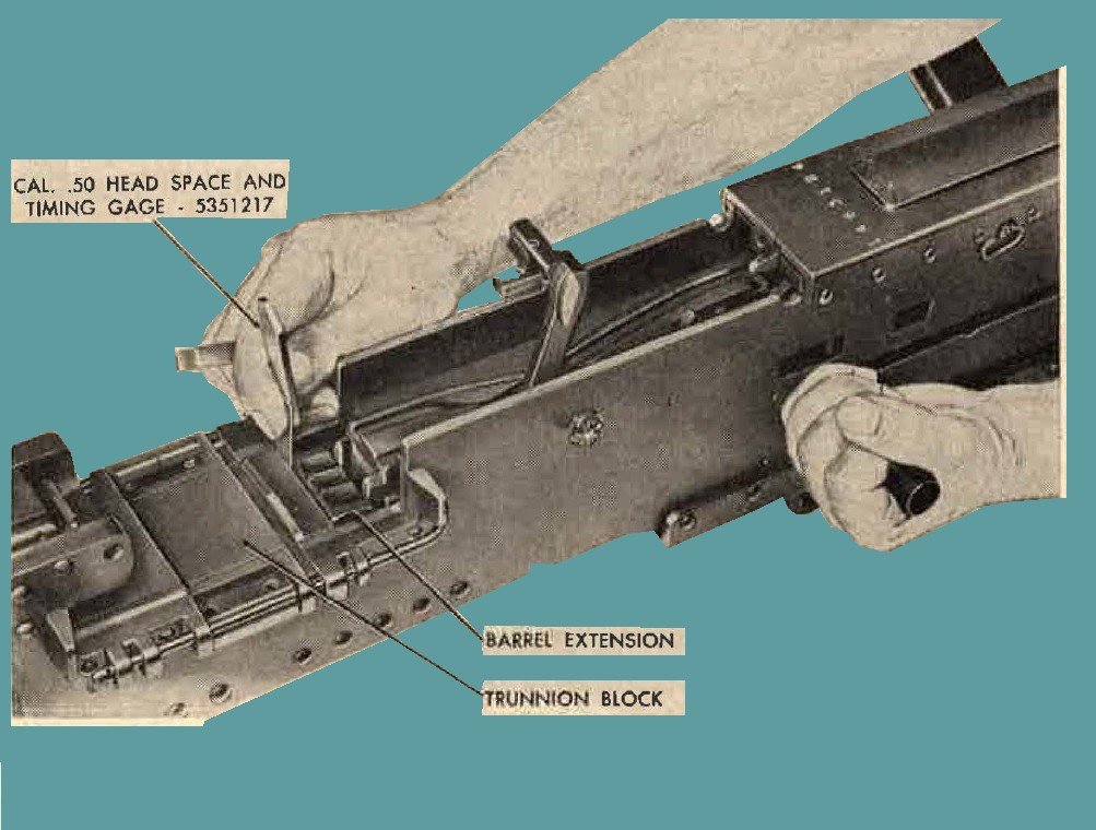
Figure 8. Using Cal. .50 ehad space and timing gage 5351217 to check timing (link chute adapter assembly removed to show operation.)
must be adjusted until the firing pin can be released with the FIRE leaf of the timing gage in place.
Note 1. A trigger bar is furnished with the gun AN-1\13 only for use with the top plate solenoid. Trigger bar and trigger bar pin must be removed and returned to stock when using a side plate solenoid or other device.
Note 2. Clearance between the trigger bar and top of bolt should not be less than 0.005 inch when the bolt is retracted 1¼ inches out of battery.
d. Checking Timing to Insure Gun Will Not Fire Too Early.
(1) If gun has been checked for FIRE on the 0.020-inch leaf of the timing gage, remove the gage by retracting the recoiling parts slightly.
(2) Cock the firing pin by fully retracting the recoiling parts and allowing them to go forward into battery.
(3) Retract the recoiling parts slighly, so that the NO FIRE (0.116 i11) leaf of the timing gage can be inserted between the barrel extension and trunion block.
(4) Allow the barrel extension to close s1owly on the gage.
(5) An attempt should be made to release the firing pin by energizing the solenoid. The firing pin should not release. If the firing pin is released, the solenoid and/or adjustable trigger bar stop should be adjusted so that the firing pin does not release.
Note. For both the FIRE and NO FIRE adjustment, the bolt must be retracted each time the solenoid is energized, whether the firing pin is released or not.
16. Changing Feed
a. General.
In order to change the gun from left-hand feed to right-hand feed, or vice versa, reporting of parts is necessary in the bolt group, cover group and certain parts of the receiver as shown in figure 9. Changing feed is outlined in b through d below.
b. Bolt Group.
(1) Remove bolt group from gttn (par. 56).
(2) Remove extractor assembly (fig. 10) by rotating it upward to a vertical position und pu1ling it from the side of the belt.
(3) Remove ejector (fig. ll) from the extractor assembly by depressing the spring-loaded ejector pin. assemble the extractor with a drift, driving out the ejector pin. Assemble the extractor with the ejector (fig. 12) and spring in the opposite posibon.
(4) Using a drifL, drive out the two bolt switch locking pins.
(5) Lift the two bolt switche, (fig. D) from the bolt and rerposition the switches by inserting them in th holes of the adjacent track. Install the switch locking pins.
(6) Install the extractor assembly in bolt and install bolt group in receiver (par. 60).
c. Cover Group.
(1) Remove belt feed slide group (par. 74a and b).
(2) Removal belt feed pawl arm and pawl assembly from the slide (par. 74e). Invert pawl assembly on slide and relocate pawl arm (fig. 13).
(3) Aline front end of belt feed lever with the slot in the cover and lift lever from stud. Transfer the belt feed lever plunger and spring to the adj acent hole in the lever.
(4) Position the belt feed lever on the lever stud and the front end over the slot of the cover. Press down on the lever until seated on the stud against cover, with plunger bearing on side of cover.
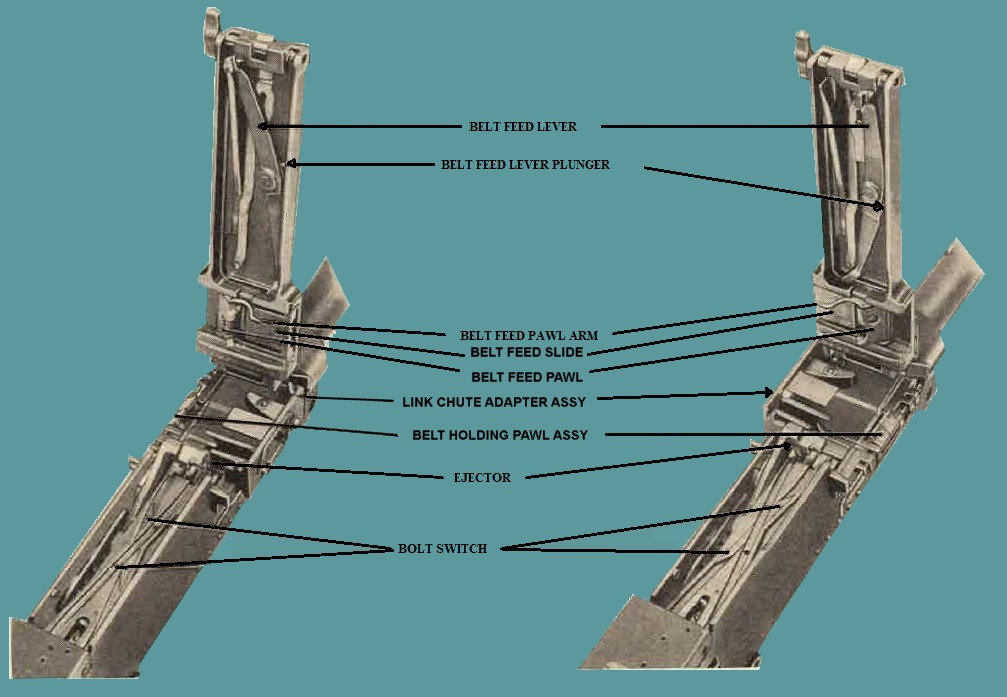
Figure 9. Position of parts for left-hand and right-hand feed.
(5) Install the belt feed slide group in its ways in cover, so that the pawl arm is towad the cover lateh. Engage the lever in the recess of the slide group, and insta11 the belt feed slide retainer and pin.
d. Receiver group.
(1) Lift link chute adapter assembly from its belt holding pawl pin assembly.
(2) Withdraw the two belt holding pawl pin assemblies, and remove the belt holding pawls, sleeve, and springs, being careful not to lose the springs.
(3) Assemble the belt holding pawls, sleeve, and springs on the opposite side of the receiver (par. 80f).
(4) Install the other belt holding paw1 pin assembly and link chute adapter assembly (par. 80g).
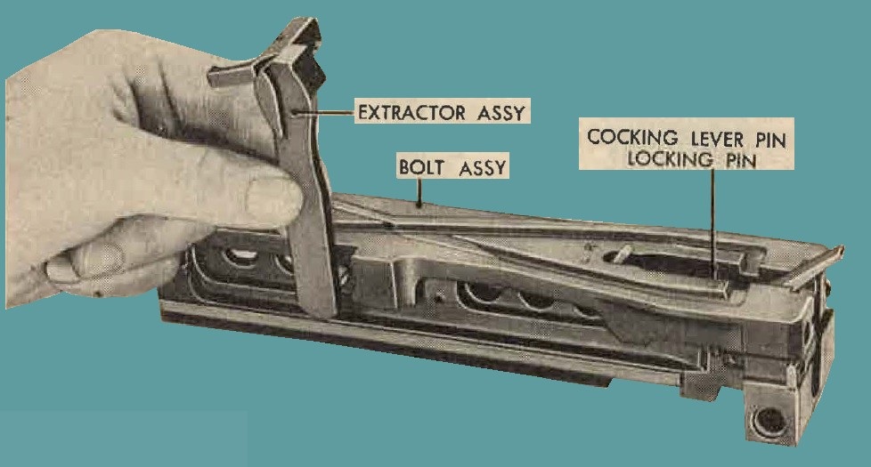
Figure 10. Removing the extractor assembly from bolt.
17. Loading Belts.
In most cases, ammunition is furnished with the proper proportions of various types of cartridges already linked in belts, as indicated on ammuniLiou containers or by the ammunition section attached to the Air Force squadron. A spot check should be made at the time the ammunition is to be loaded in the gun to insure that the cartridge are properly seated in the belt. When it is necessary to load the cartridges into the links to form belts, to join belts or to reposition cartridges in belts, it may be done by means of the cal. .50 dieconnector coupler M20- 7146365 (fig. 20) or cal. .50 link-delinking machine M7- 7160003 (fig. 22). Linking, delinking, and repositioning of belt ammunition by means of other type Iinking and repositioning machines are explained in TM 9-218 and TM 9-220.
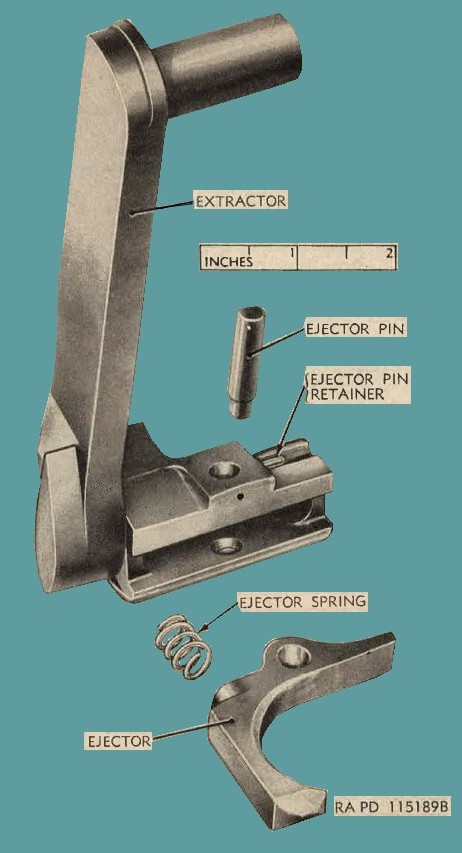
Figure 11. Retractor assembly - Exploded view
18. Loading, Feeding, and Chambering.
a. Definition.
(1) Loading refers to the placing of a loaded belt into the feedway of the gun.
(2) Feeding includes any mechanical action, subsequent to loading, that extracts a round from the belt and places it in the T-slot of the bolt.
(3) Chambering is the seating of the round in the chamber.
b. Procedure.
(1) Check to see that ammunitiou is properly loaded in the belt. Check appropriate Air Force technical orders to see that the belt, ammunition box, link chute adapter assembly, etc., are in proper alinement and securely assembled.
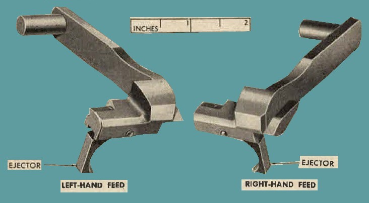
Figure 12. Comparison of extractor assembly for left-hand and right-hand feed.
(2) With the cover open, lay the first round, double-loop end of belt leading, in the feedway beyond the belt holding pawls or, if installation does not permit opening of cover, enter the double-loop end of the belt through the feed opening unthl the first cartridge is beyond the belt holding pawls.
(3) If opeu, close the cover, fully retract the bolt, and allow it to go forward freely . This places the first cartridge in the belt in position in the feedway where it is gripped by the extractor.
(4) Retract the bolt once again completely to the rear and release it. This action chambars the fast cartridge, and the extractor grips the next cartridge in the belt.
(5) The gun is now fully loaded, cocked, and ready to fire when the firing mechanism is actuated.
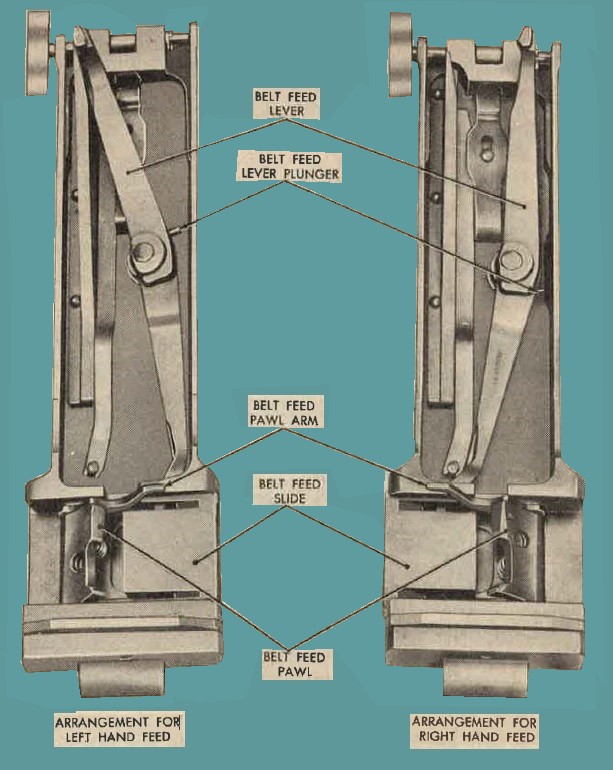
Figure 13. Arrangement of cover group parts for left-hand and right-hand feed.
19. Firing.
a. Firing Devices.
The gun AN-M3 is equipped with a fixed backplate without manual trigger and is fired by means of a top plate or side plate solenoid assembly. These items are furnished by the Air Force and are covered in the Air Force technical orders. If gun is to be fired by means of a solenoid mounted on the side p]ate, the square end of the sear, slide must be inserted on the same side of the bolt from which the gun is to be fired. For present design bolt, assemble the sear slide, sear slide stop pin, and cocking lever pin on the side from which the gun is fired. For present design modified bolt, insert the cocking lever pin (fig. 14) from the opposite side from which the sear slide and sear slide stop pin are assembled.
b. Maximum Single Burst.
The maximum single burst that may be fired without danger of "cook-off" is 200 rounds. Caution: If a burst of more than 200 rounds is fired, the gun should be cleared within 10 seconds after completion of burst. If the gun cannot be cleared within 10 seconds, the round should be allowed to remain in the chamber a minimum of 5 minutes, making sure the gun is aimed in the opposite direction from personnel and equipment. If an attempt is made to clear the gun before the 5-minute period has elapsed, the extracted cartridge may explode outside the weapon, causing serious injury to personnel or equipment.
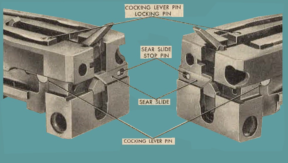
Figure 14. Position of sear slide for solenoid mounted on the left and right side.
c. Barrel performanoe Data.
Machinegun AN-M3 has a lined, plated barrel that has a far greater life than plain steel barrels. This barrel has a special metal liner, approximately 9 inches in length, located just ahead of the chamber. For identification, visual inspection will show a ring in the bore where the liner ends. In addition, the bore is chromium-plated ahead of the liner. This treatment of the barrel gives it exceptional velocity and accurate barrel life but does not affect the "cook-off" point, which is approximately the same as for ordinary steel barrels.
d. Correction of Malfunctions and Stoppages.
(1) A stoppage is the result of a malfunction caused by an improper or incomplete action of some part of the gun, its equipment, or ammunition. Malfunctions, their probable causes and corrective action are covered in table III.
(2) When a gun stops firing or fails to fire, the first concern of the gunner is to get the gun back into action in th0 shortest possible time. Attempt. to charge gun and, if gun can be charged, attempt to fire.
(3) If the gun cannot be charged and the cove.r is accessible, open the cover and inspect for links jammed on link stripper of adapter assembly or other types of malfunctions that would prevent the charging of the gun (table II). Correct, close cover, charge gun, and attempt to fire gun. If firing still cannot be resumed, the trouble will have to be corrected when the plane returns to base.
(4) Stoppages, which cannot be immediately analyzed as to their cause, must be reported to the armament officer, under whose supervision the materiel is maintained.
e. Misfires and Cook-Offs.
Energize the solenoid two or three times. If the attempts to fire fail, wait 10 seconds before retracting the bolt to avoid the possibility of a delayed explosion taking place after the cartridge has been removed from the chamber.
Caution: I£ the barrel is hot and the cartridge cannot be fired, the cartridge must be allowed to remain in the chamber for a minimum of 5 minutes because of the possibility of a cook-off. Cook-offs normally take place between 10 seconds and 5 minutes after the round is chambered in a hot barrel. If the round is removed too soon, there is danger that the extracted round will explode outside the gun. However, it is safe to fire the round in the barrel during this interval.
20- Unloading.
a. Open the cover, raise the extractor assembly, and remove the ammunition belt.
b. Lower extractor assembly and retract the bolt sufficiently to remove the round from the chamber. Make a visual inspection of feedway, T-slot, and chamber to be sure the gun is unloaded. Release the bolt and close the cover.
c. When certain that the gun is completely unloaded, release the firing pin by actuating the sear or sear slide to relieve compression on the firing pin spring.
Caution: Before raising the cover, be sure that firing circuits arti placed in the SAFE position, so that the gun cannot be fired accidentally.
21. General.
a. The mechanical steps of operation under unusual conditions are the same as for operation under usual conditions, as explained in paragraphs 12 through 20. The only difference in procedure is the servicing of the gun with regard to cleaning and lubrication to insure proper functioning where extremes of atmosphere, temperature, and humidity occur. Special care should be observed with regard to cleaning and lubrication of the gun, as explained in this section. Such care is most necessary to insure proper operation and functioning of the mechanisms and to guard against excessive wear of the moving parts and deterioration of the materiel.
b. Under any conditions, the bore and chamber of the barrel must be thoroughly wiped free of excess oil before firing or mounting the gun in the airplane for combat (par. 34).
a. Under certain conditions, as in high-altitude flights, heaters are required.
22. Extreme Cold Weather Operation.
a. In temperatures below freezing, it is essential that all moving parts of the machinegun be kept absolutely free of moisture. Excessive oil on the working parts will solidify to such an extent as to cause sluggish operation and functioning or complete failure. This applies in particular to the firing mechanism and small spring-operated parts. Special care should be taken to eliminate all grease, excess oil, and fouling from the following parts and assemblies:
(1) Recoil booster and muzzle end of barrel.
(2) Belt feed pawl and belt holding pawl springs and seats.
(3) Bore and chamber of the barrel.
(4) Driving spring rod with springs assembly and its tunnel in bolt.
(5) Belt feed lever plunger, spring, and seat.
(6) Firing pin extension group and its tunnel in bolt.
(7) Extractor (side plate) switch, including side plate switch recess.
(8) Barrel buffer assembly.
b. If guns are left mounted in the airplanes, the exposed parts should be carefully covered for protection and to prevent frosting.
a. When guns are removed from the airplane and taken into a warmer area, such as a heated building, water vapor will condense upon the cold surface. This condition is known as "sweating." It can be prevented as indicated in (1) through (6) below.
(1) Do not bring any cold materiel indoors unless it is absolutely necessary. It is best to leave it outdoors but protected from the elements with proper covers.
(2) If it is necessary to bring guns or other equipment from low temperatures to room temperatures, the use of anticondensation containers is recommended. These containers can be specially made tight-fitting cloth-framed boxes or any other fairly airtight containers with heat conducting walls. Place the cold equipment in the container. Have container at outside temperature, so that it will contain cold dry air. Close the top, bring it indoors, and allow it to warm up. The cold dry air expands as it warms, breathing outward, and therefore no warm humid air from the room comes in contact with the materiel and there is no condensation on it. ·when the materiel is entirely at room temperature, sweating will not occur when it is removed from the container.
(3) If condensation occurs on the gun, it must be disassembled (par. 9), cleaned, thoroughly dried, and lubricated after it reaches room temperature to prevent rust or corrosion. Do not operate the materiel before thoroughly drying, as the moisture will form an emulsion with the oil or grease, necessitating removal of the emulsified lubricant and lubricating the ma,teriel. Do not move materiel having moisture caused by condensation on it into the outdoor temperature, as the parts will become covered with frost and may not function.
(4) If guns are to be mounted in the airplane immediately, they should be coated with special preservative lubricating oil as outlined in paragraphs 33 and 34.
(5) If the guns are not to be mounted in the airplane immediately, special preservative lubricating oil should be used to prevent rusting. The guns should be inspected every 60 days and lightly lubricated as outlined in paragraphs 33 and 34. Note. Great care should be used to insure the removal of all excess oil from the guns, especially from moving parts. Firing pin spring, driving springs, tunnels in bolt in which they operate, switch recess, springs and spring seats, sear, and like places also should be free of excess oil. Excess oil will congeal at low temperatures and cause sluggish action or even malfunction of the gun.
(6) Remove all excess oil from bore and chamber before firing.
23. High-Altitude Flights.
a. when airplanes are operated in moderate climates at high altitude where extremely low temperatures are encountered, condensation of moisture may occur on the guns when returned to ground temperature. In such cases, guns should be inspected, disassembled, dried, cleaned, and lubricated as prescribed in paragraph 22. When high altitude flights are anticipated, guns should be lubricated very sparingly. Thoroughly remove all excess oil from bore and chamber before firing.
b. The electric heaters assembled to some machineguns mounted in aircraft are Air Force equipment. Their purpose and operation are covered in Air Force technical orders.
24. Operation in Extreme Hot Weather Conditions.
a. In hot climates, the thin film of oil necessary £or machineguns under combat conditions will be quickly dissipated. Inspect guns frequently and renew oil film as often as is necessary to prevent rusting and assure the gun being ready £or combat when kept m.ounted in the airplane. Clean guns frequently to remove dust or grit that will stick to oiled surfaces.
b. Keep guns covered as much as possible.
c. Perspiration from the hands is a contributing factor to rusting, because perspiration contains acid. When handled, guns should be wiped dry frequently and the oil film maintained.
d. When guns are not to be mounted in the airplane immediately, they should be cleaned with rifle-bore cleaner and then lubricated with special preservative lubricating oil. Inspect guns every 60 days. Before mounting guns in the airplane for combat, they should be cleaned with rifle-bore cleaner, wiped dry, and lubricated as outlined in paragraphs 33 and 34. Remove all excess oil from bore and chamber before firing.
e. ·where humidity is high, take special care to inspect unexposed surfaces, such as the bore and chamber, inside the barrel jacket, receiver, springs and spring seats, firing pin and driving springs, tunnels in bolt, and like places where rusting 1ni.ght occur and not be quickly noticed. Inspect screws and pins frequently to prevent rust attacking and "freezing" them in place.
25. Operation Under Sandy or Dusty Conditions.
a. In localities where dust and sand storms are prevalent, guns should be kept carefully covered at all times, whether mounted in the airplanes or not. Dust and sand will stick on lubricated surfaces, forming a gummy paste, which may clog the gun and cause malfunction. This paste will also act as an abrasive and cause undue wear of the moving parts of the gun. Under such conditions, remove guns from the airplane as often as practical and thoroughly clean and lubri::ate them. Lubricating should be confined to moving parts and contacting surfaces and should be as light as possible for proper functioning of the gun.
b. After a dust or sand storm, guns should be disassembled and thor011ghly cleaned, inspected, and lubricated as in a above. Remove all excess oil from bore and chamber before firing.
26. Operation Under Moist or Salt Atmosphere Conditions.
a. Salt moist air is conducive to quick rusting, as the salt has a tendency to emulsify the oil and destroy its rust-preventive qualities. When mounted in the airplane, guns should be kept lightly lubricated and inspected frequently and treated in a manner similar to that prescribed for guns in paragraph 24.
b. If the guns are not to be mounted in airplanes immediately, clean them thoroughly with rifle-bore cleaner and lubricate with special preservative lubricating oil. Inspect guns every 60 days. Inspection should be thorough, with particular att.ention given to nnexposed parts as prescribed in paragraph 24e.
c. Before mounting guns in the airplane, they should be thoroughly cleaned to remove all excess oil and then lubricated as outlined in paragraphs 33 and 34. Remove all excess oil from bore and chamber beforn firing.
27. General.
Tools, equipment, and spare parts are issued to the using organization for maintaining the materiel. Tools and equipment should not be used for pmposes other than prescribed and, when not in use, should be properly stored in the chest and/or roll provided for them.
28. Parts.
Organizational spare parts are supplied to the using organization for replacement of those parts likely to become worn, broken, or otherwise unserviceable, providing such operations are within the scope of organizational maintenance functions. Organizational spare parts, tools, and equipment supplied for the cal. .50 basic aircraft machinegun AN-M3 are listed in Departmeut of the Army Supply Manual ORD 7 SNL A-G7, which is the authority for requisitioning replacements.
29. Common Tools and Equipment.
Standard and commonly used tools and equipment having general application to this materiel are listed in ORD 6 SNL J-10, section 2, and are authorized for issue by TA and TO&E. They are not specifically identified in this manual.
30. Special Tools and Equipment.
Certain tools and equipment specifically designed for operation, organizational maintenance, repair, and general use with the materiel are listed in table I for information only. This list is not to be used for requisitioning replacements.
Table 1. Special tools and equipment for operation and organizational maintenance.
| Number | ITEM | Identifying No | References | Unit | |
| Fig. | Par. | ||||
| 1 | BRUSH, cleaning, Cal. .50, M4. | 5504037 | 15 | 39b (1) | To clean bore. |
| 2 | BRUSH, cleaning, chamber, M6 (bristle). | 0108828 | 15 | 7b(5) (d) | To clean the chamber of the gun. |
| 3 | BRUSH, cleaning, firing pin hole, Cal. .50. | 7162702 | 15 | 10c, 58d | Used with cal. .45 cleaning rod M4 - 5564102 to clean firing pin hole in bolt. |
| 4 | CASE, jointed cleaning rod and brush, cal. .50, M15. | 5564274 | 16 | ----- | To store cal. .50 jointed cleaning rod M7-6535441 and cal. .50 cleaning brush M4-5504037. |
| 5 | COUPLER, disconnector, cal. .50. | 7146365 | 20, 23 | 17, 31 | To remove, insert, or aline cartridges. |
| 6 | COVER, muzzle, cal. .50, M337. | 7162183 | ----- | ----- | ----- |
| 7 | END, cleaning patch | 7162704 | 15 | 10c | Used with cal. .45 cleaning rod M4-5564102 to clean the firing pin hole in bolt. |
| 8 | GAGE, bbl erosion, cal. .50, M6E1 | 7319970 | 21, 68 | 70h | To detect excessive barrel erosion. |
| 9 | GAGE, head space and timing, Cal. .50. | 5351217 | 7, 8, 17 | 14, 15 | To check head space and timing of gun. |
| 10 | HANDLE, bolt | 6008583 | 20 | 36f | To hand-operate gun. |
| 11 | MACHINE, link-delinking, hand, cal. .50, M7. | 7160003 | 22 | 17, 32 | To link or delink cartridges. |
| 12 | REFLECTOR, bbl, cal. .50. | 5564255 | 15 | 70h(2) | To inspect bore of gun. |
| 13 | ROD, cleaning, cal. .45, M4 (pistol). | 5564102 | 16 | 10c, 58d | Used with cal. .50 firing pin hole with cleaning brush 7162702 or cleaning patch end 7162704 to clean the firing pin hole in bolt. |
| 14 | ROD, cleaning, cal. .50, M6 | 6535442 | 16 | ----- | Used with bore-cleaning cloth to clean gun tube. |
| 15 | ROD, cleaning, jointed, cal. .50, M7 | 6535441 | 16 | 7b(5)(c), 39b(1). | Used with cal. .50 cleaning brush M4-5504037 to clean the bore. |
| 16 | TOOL, comb assembling and disassembling, cal. .50. | 7265946 | 19 | 52f, 57k | ----- |
| 17 | TOOL, depressor, plunger adjusting screw, cal. .50. | 7265950 | 19, 40 | 52c | To depress adjusting screw plunger when removing or installing backplate adjusting screw. |
| 18 | TOOL, release, buffer spring lock, lgh 10 in, cal. .50. | 7161816 | 17 | 62b | Used to remove the body and buffer assembly from receiver. |
| 19 | TOOL, removing, firing pin spring, cal. .50. | 6243646 | 17, 51 | 57k, 59b | To remove and install firing pin spring |
| 20 | TOOL, trunnion adapter | 7265626 | 18,80 | 78i, 80h | To remove and install trunnion adapter |
| 21 | WRENCH, comb, cal. .50. | 7161767 | 19,40,78. | 52c, 54d, 78h, 80a. | To remove and install recoil booster and backplate adjusting screw. |
31. Cal. .50 Disconnector Coupler M20
The cal. .50 disconnector coupler M20 (fig. 20) is used to remove or install cal. .50 rounds in metallic-link belts and at the same time aline them properly. To extract a round, the round to be removed is placed near the end of the disconnector coupler (fig. 23) with the end of the tool bearing against the link and the bent projection in the extraction groove. compress disconector coupler to remove round. To install round place links on tool with nose of round in links. Compress disconnector coupler fully and round will be properly seated in belt.
32. Cal. .50 Link-Delinking Machine M7-7160003
This machine (fig. 22) can be used to delink and link ammunition in a cal. .50 metallic-link belt. In general, the machine consists of a base, handle, slide, and delinker and is operated as described in "a" and "b" below.
a. To delink ammunition, partly raise the handle and lay the belted ammunition on the base with the separating pins between the cartridges and the links against the pins. Then lower the handle until the delinker engages the extractor grooves in the cartridges; hold the delinker in position and raise the handle. This will cause the delinker to move rearward and pull the cartridges from the links.
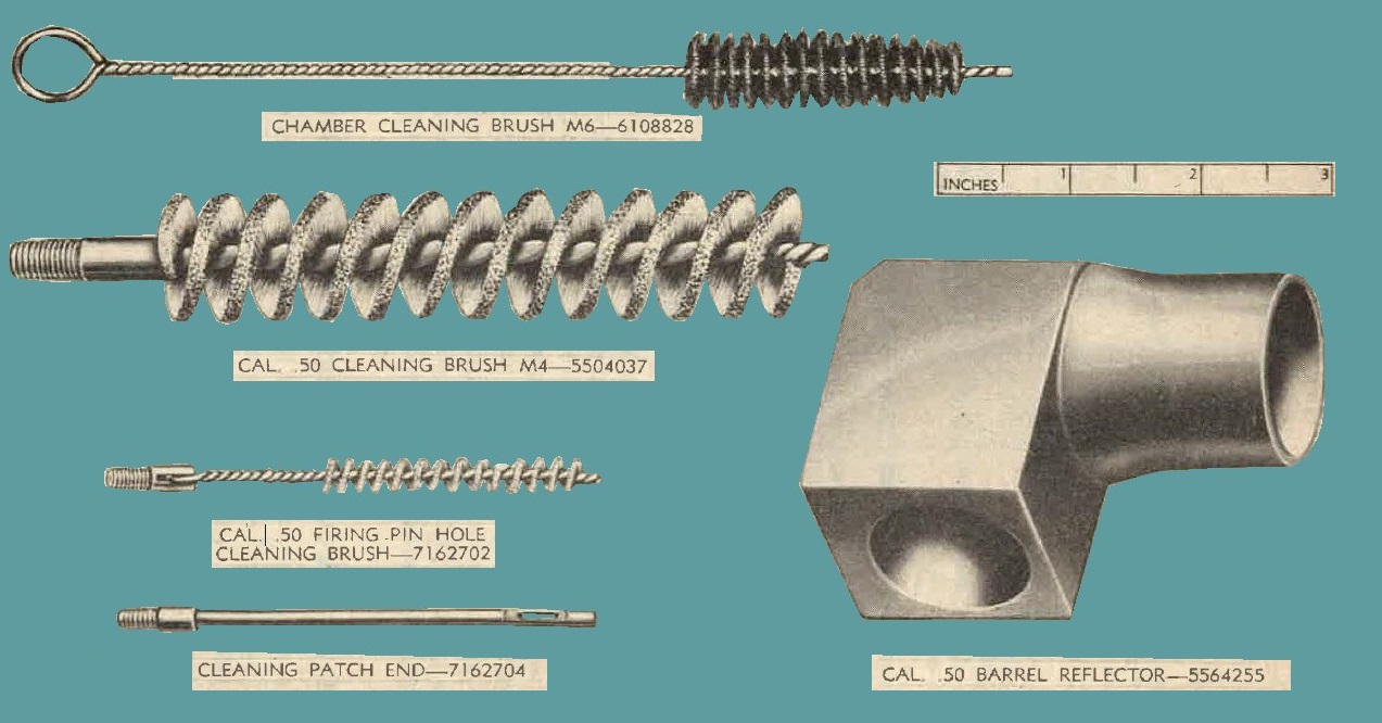
Figure 15. Cleaning brushes, patch end, and barrel reflector.
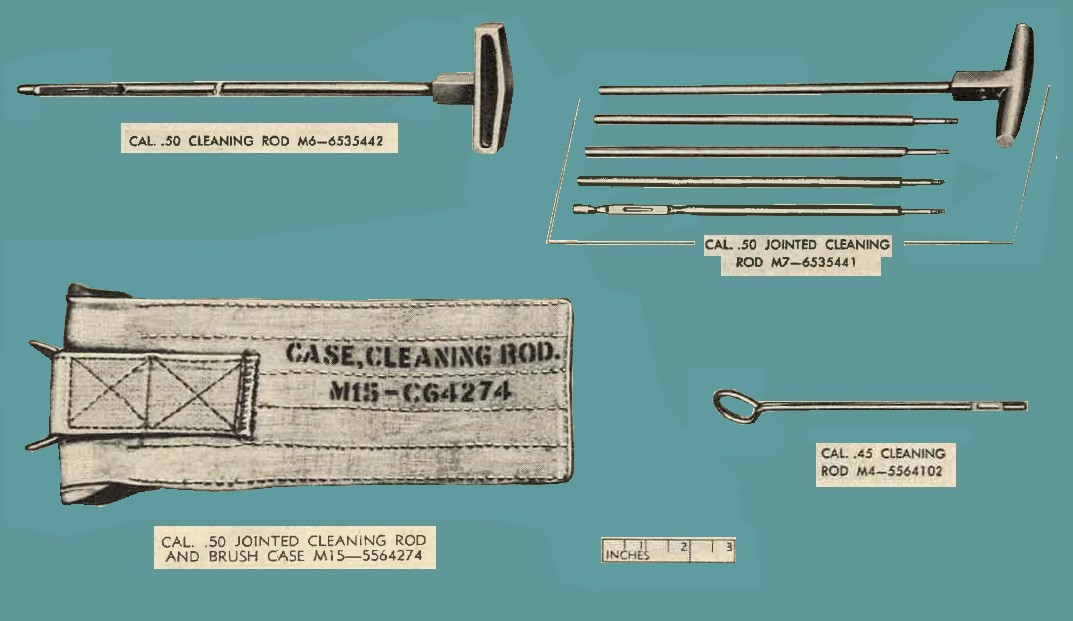
Figure 16. Cleaning rods and rod case.
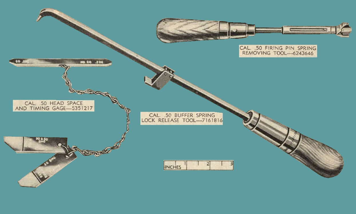
Figure 17. Head space and timing gage, and tools for buffer spring lock and firing pin spring.
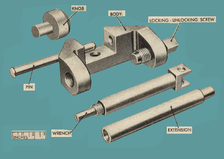
Figure 18. Trunnion adapter tool 7265626
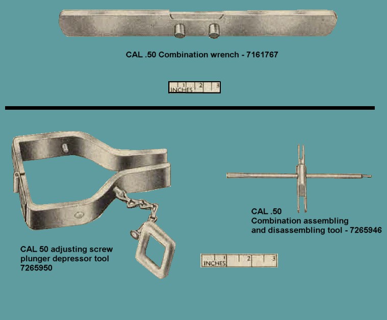
Figure 19. Combination wrench, adjusting screw plunger depressor tool, and combination tool.
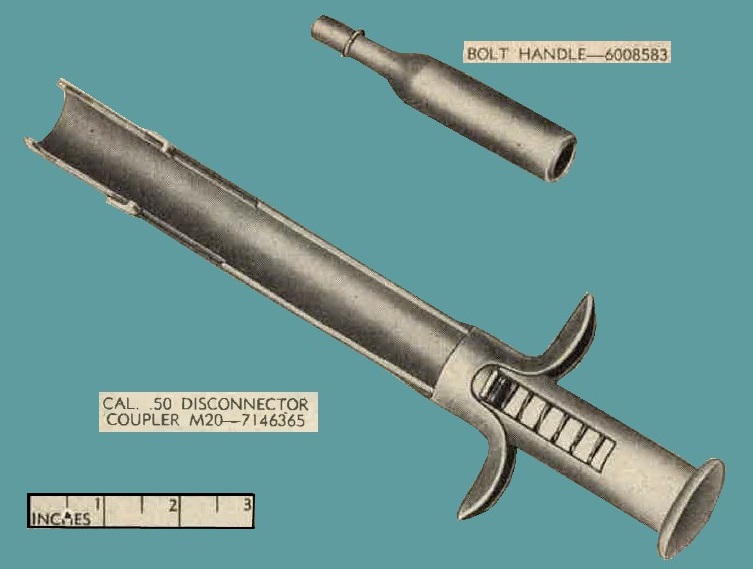
Figure 20. Disconnector coupler M20-7146365 and bolt handle - 6008583.
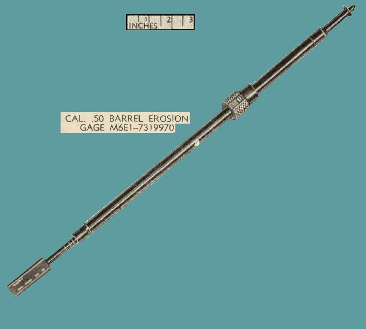
Figure 21. Cal. .50 barrel erosion gage M6E1 - 7319970
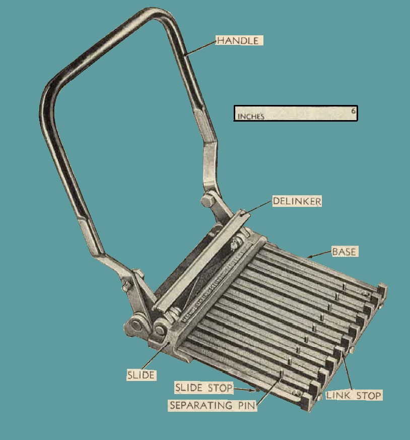
Figure 22. Cal. .50 link-delinking machine M7-7160003.
b. To link ammunition, properly assemble links and place on base adjacent to the U-shaped link stops; then place cartridges in the grooves of the base and start them into the links. With delinker raised, lower the handle until the slide presses against the base of the cartridges and forces them forward into the links. Move handle clown until slide is checked by the slide stops on the sides of the base. The cartridges will then be loaded to the correct depth in the links. Care should be taken to position properly that portion of the loaded
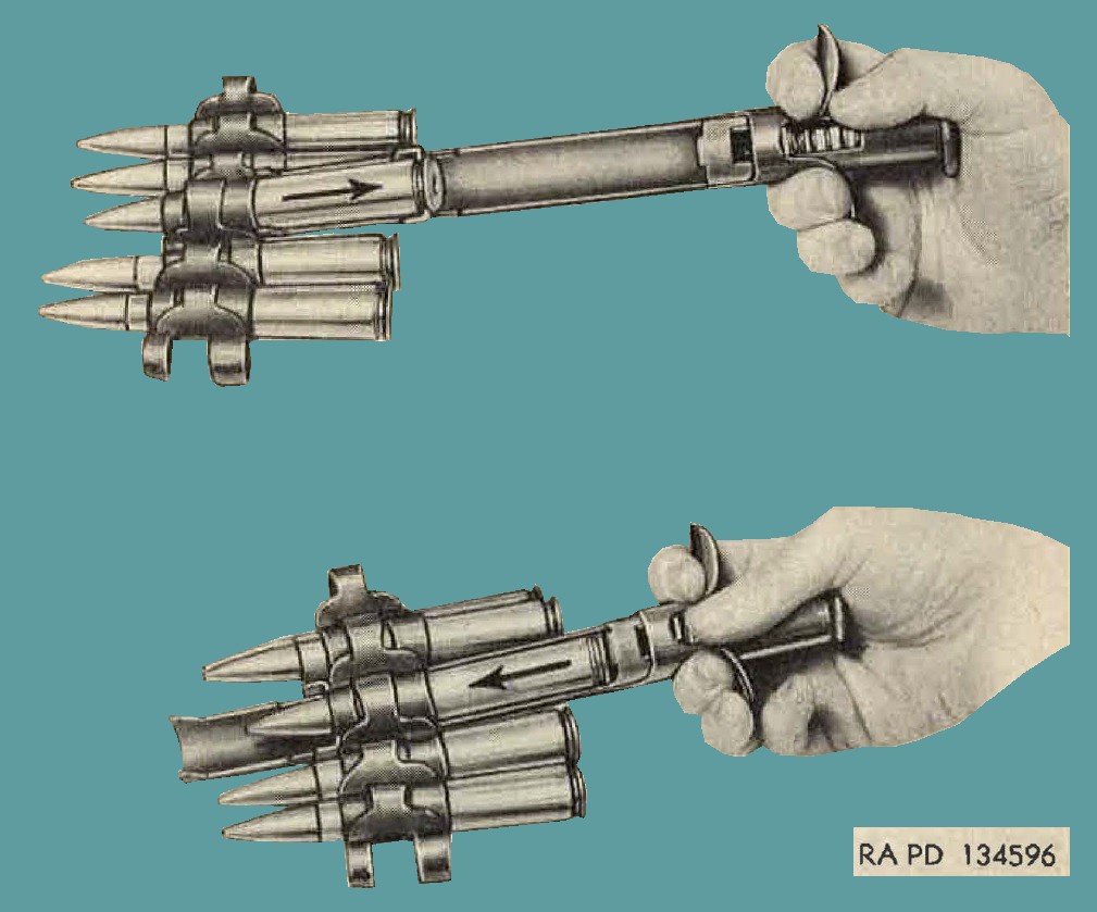
Figure 23. Installing and removing round, using cal. .50 disconnector coupler M20-7146365.
belt that is adjacent to the section being loaded. Correct position of cartridges in links is shown in figure 97. Pivot pins should be cleaned and lubricated occasionally to insure smooth action; wipe dry of excess oil.
33. Lubrication Order
LO 9-219 (fig. 24) prescribes organizational lubrication maintenance. In addition, it prescribes the lubricants to be used under various conditions.
34. General Lubrication
The lubrication procedures are described in a through e below.
a. Special preservative lubricating oil is used to lubricate the gun at all times to insure proper functioning at all temperatures.
b. Lubrication should be accomplished carefully and sparingly. All excess oil should be wiped from the gun. This is particularly important with regard to the bolt, barrel buffer assembly, and chamber of barrel.
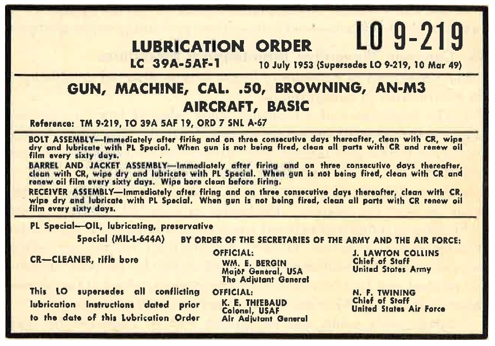
Figure 24. Lubrication order.
Caution: Oil or grease in chamber of the barrel will raise the breech pressure to a hazardous point when the gun is fired and may result in serious injury to personnel.
c. Excess oil holds grit and foreign matter blown on the gun and as a result may clog the recoiling parts and cause a malfunction or stoppage. In any case, the abrasive action of the grit and foreign matter will cause excessive wear of the moving parts.
d. Smoking of the gun when firing may indicate excessive lubrication.
e. Remove excess oil from the bore and chamber of the barrel before firing or mounting guns for combat. Note. The term "lubrication" as used in this manual applies both to lubricating moving contacting surfaces to minimize friction and to covering stationary parts with an oil film to prevent corrosion.
35. General.
Preventive maintenance services prescribed by Air Force and Army regulations are a function of organizational units or armorers, and their performance is the responsibility of the armament officers of such orgnnizations. These services consist generally of preflight, postflight, and major services performed by organizational maintenance personnel. This section contains important general preventive maintenance procedures and specific maintenance procedures applying to the gun as a whole. Special maintenance of specific groups of the gun is covered, when necessary, in sections pertaining to the groups.
36. Common Preventive Maintenance Procedures.
The procedures in "a" through "f" below will be observed in addition to the information in paragraph 3D.
a. The importance of a thorough knowledge of how to clean and lubricate the materiel cannot be overemphasized. The kind of attention given to this gun largely determines whether the gun will shoot accurately and function properly when needed.
b. Rust, dirt, grit, gummed oil, and water cause rapid deterioration of all parts of the weapon. Particular care should be taken to keep all bearing surfaces and exposed parts clean and properly lubricated. wiping cloths, rifle-bore cleaner, dry-cleaning solvent or volatile mineral spirits, and lubricants are fnrnished for this purpose. Remove all traces of rust from surfaces with crocus cloth, which is the coarsest abrasive to be used by organizational personnel for this purpose.
c. Spare parts, tools, and equipment will be inspected for completeness, serviceability, and interchangeability. Missing or damaged items will be replaced or turned in for repair. Use only tools that are provided and see that they fit properly.
Caution: Tools that do not fit will fail or cause damage to parts.
d. At least every 6 months, a check will be made to see that all technical orders have been applied. Check AF Form 185 for completeness. A list of current teclmicnl orders is published in TO 00-1-39. If a technical order has not been applied, the local armament officer will be promptly notified. No alteration or modification will be made except as authorized by official publications.
e. Each time the gun is disassembled for cleaning or repair, carefully inspect all parts for cracks, excessive wear, rust, and like defects, which might cause a malfunction of the gun. See paragraphs 49 and 50 for information on certain parts that, when worn, damaged, or improperly adjusted, cause definite malfunctions. Use this section as a guide during inspection. Thoroughly clean and properly lubricate all parts before assembly. Also, replace all springs that are broken or kinked.
f. Each time a gun is assembled it should be given an operational check after head space and timing have Leen checked. This check consists of operating the gun by hand, using the bolt handle 6008583 (fig. 20). When possible, a belt of dummy cartridges should be fed through the gun to check feeding, extracting, chambering, and ejection.
37. Inspection and Rebuild Schedule.
a. Purpose. To insure proper functioning and maximum efficiency of the gun AN-M3 under combat conditions, the inspection and rebuild schedule will be adhered to as outlined in b below.
b. General information.
(1) Normal periodic inspections will continue to be made, and worn or defective parts noted will be replaced. In addition, a thorough inspection of each weapon will be made ·after 5,000 rounds have been fired and again after 10,000 rounds have been fired, paying special attention to parts outlined in (3) and (4) below.
(2) All parts replacements will be recorded on AF Form 185 under the heading "Maintenance and Performance Record," utilizing all columns as for entries reflecting malfunctions.
(3) Inspect the following parts at 5,000 and 10,000 rounds and replace if worn or defective:
| NUMBER | PART NUMBER | DESCRIPTION |
| 1 | 7162763 | EXTENSION, firing pin, assy inspect for cracks or worn sear engaging notch. |
| 2 | 7265110 | SEAR. Inspect for cracks or worn sear notch. |
| 3 | 7312709 | SLIDE, sear. Inspect for cracks at sear slide pin hole. |
| 4 | 7265183 | STOP, firing pin spring, assy. Inspect for cracks at bend and at section where pin is riveted. |
| 5 | 7312692 |
ROD, driving spring, with spring, assy.
Inspect for condition of spring. Retaining pins should be tight. |
| 6 | 7313449 |
SPRING, washer, backplate buffer, group assy.
Inspect springs for cracks, fractures, or burns. |
| 7 | 7266301 | SPRING, backplate. Inspect spring for cracks or fractures. |
(4) At 5,000 and 10,000 rounds, the receiver assembly will be checked with care, with special attention given to tho following riveted parts:
| NUMBER | DESCRIPTION |
| 6128730 | BRACKET, belt holding pawl. |
| 7265160 | BRACKET, top plate. |
| 7812745 | DEPRESSOR, breech block, left-hand. |
| 7312744 | DEPRESSOR, breech block, right-hand. |
Weapons with loose rivets should not be fired but should be withdrawn from service and tagged for depot (arsenal) rebuild.
(5) Upon completion of 15,000 rounds firing, the machinegun AN-M3 will be withdrawn from service and tagged for depot (arsenal) rebuild. Inspectors classifying guns for depot rebuild will record all deficiencies on AF Form 185 at the time of inspection.
Note. Guns forwarded for rebuild must be complete.
38. Cleaning.
See paragraph 11 for information regarding cleaning guns in use. In addition, see paragraph 100 for information regarding the use of the tools furnished for cleaning the gun.
39. Specific Procedures.
a. Before-Firing.
(1) Thoroughly clean the bore and chamber of all dirt, oil, or foreign matter.
(2) Wipe off surplus oil from bolt, feedway, and cover assembly using a clean wiping cloth wet with proper oil and then wrung out.
(3) Wipe outer surfaces of gun, using a clean wiping cloth wet with proper oil and then wrung out.
b. After-Firing.
(1) Bore and ohamber. The cleaning procedure in (a) and (b) below is to be followed at the end of the day's firing. If no further firing is anticipated, it is to be repeated on 3 consecutive days thereafter.
(a) Place two cleaning patches in the slot of the cal. .50 jointed cleaning rod M7-6535441 (fig. 16); saturate the patch with rifle-bore cleaner and move the rod with patches back and forth through the barrel several times. If rust or foreign matter are not removed by the rifle-bore cleaner, attach a, cal. .50 cleaning brush M:4--5504037 (fig. 15) to the cleaning rod and run the brush through the barrel several times. Make certain that the brush goes all the way through the barrel before reversing direction. A light coating of special preservative lubricating oil should be allowed to remain in the bore and chamber between cleanings to prevent rust.
(b) After fourth cleaning following firing, if no firing is anticipated within the next 24 hours, place clean dry patches in the slot of the cleaning rod and thoroughly dry bore and chamber. Wet clean dry patches with special preservative lubricating oil, then wring out and apply a light film of oil to the bore and chamber by running the patches through the bore.
Note. Remove excess oil from bore and chamber if guns are to be fired.
(2) Parts other than barrel.
(a) With rifle-bore cleaner, thoroughly clean all surfaces that have been exposed to powder gases, namely, the face of bolt, trunnion block, cover, and interior of receiver.
(b) During tiring, hard carbon gradually accumulates in the recoil booster. This carbon deposit must be carefully removed with scraper or crocus cloth and the parts lubricated immediately.
(o) Dirt and foreign matter must be removed from all other parts. Thoroughly dry all components and immediately apply a light coating of special preservative lubricating oil. Handle cleaned parts with gloved hands, as acid from the hands accelerates corrosion.
c. Service for Periods Up To 60 Days. If the guns have not been fired, clean all parts with rifle-bore cleaner, wipe dry, and renew oil film with special preservative lubricating oil every 60 days. Before mounting guns in the airplane for combat, clean all parts with riflebore cleaner, wipe dry, and lubricate as outlined in paragraphs 33 and 34. If use of the gun is not anticipated for 90 days, it may be placed in limited storage as outlined in paragraph 126a.
d. Care of Spare Parts, Tools, and Equipment. Complete sets of spare parts, tools, and equipment will be maintained at all times, kept lubricated to prevent rusting, and inspected at frequent intervals. In the event tools and equipment should need cleaning, they should be cleaned by the vapor degreaser, if available, or dry-cleaning solvent or volatile mineral spirits. Keep lightly lubricated with special preservative lubricating oil at all times.
40. Preventive Maintenance Schedule.
The items or points to be inspected and serviced at scheduled times are listed in table II, with cross-references to detailed instructions in other paragraphs in this manual.
Table II - Preventive Maintenance Schedule.
| PREVENTIVE MAINTENANCE | DETAILED INSTRUCTIONS | |
| Gas as unit |
Preflight or before firing.
Check for proper lubrication and cleanliness. |
Pars 11, 33, and 34. |
| Head space and timing. | Check | Pars 14 and 15. |
| Ammunition belt. | Check for proper loading and alinement. | Par 18. |
| Ammunition boxes, feed chutes, and link chute adapters. | Check for proper alinement. | Par. 18. |
| Feedway. | Check to see that the gun is properly loaded. | Par. 18. |
| Postflight or after-firing | ||
| Malfunctions or stoppages | Check for type. | Par. 50. |
| Check head space and timing. | Check | Pars. 14 and 15. |
| Gun as a unit. | Unload and record number of rounds fired. | Par. 8b. |
| Bore and chamber and all working parts. | Inspect, clean and oil. | Par. 39. |
| Assembled gun. | Check operation. | Par 36f. |
41. General.
a. The gun AN-M3 may be fired by a top plate solenoid, acting upon the trigger bar to depress the sear, or by a side palte solenoid, acting upon the rear slide to depress the sear. In any case, the functional operation of the gun is the same. For clarity illustrations in this section show the sear operated by a trigger bar.
b. Each time a cartridge is fired, recoil force starts the movement of related parts in their proper oeder. The action of these parts and their relationship can be explained more clearly if each cycle of operation is divided into various phases. These phases will be explained in paragraphs 42 to 48 in the order indicated in "c" below. Familiarity with the construction of the gun and function of its component parts is necessary for a tborough understanding of the cyclic functioning of the gun as a whole. It will aid in understanding cyclic functioning if the gun is hand operated usiug dummy ammunition Figure 25 shows a cutaway view of the unloaded gun, with the recoiling parts in the fonward or BATTERY position.
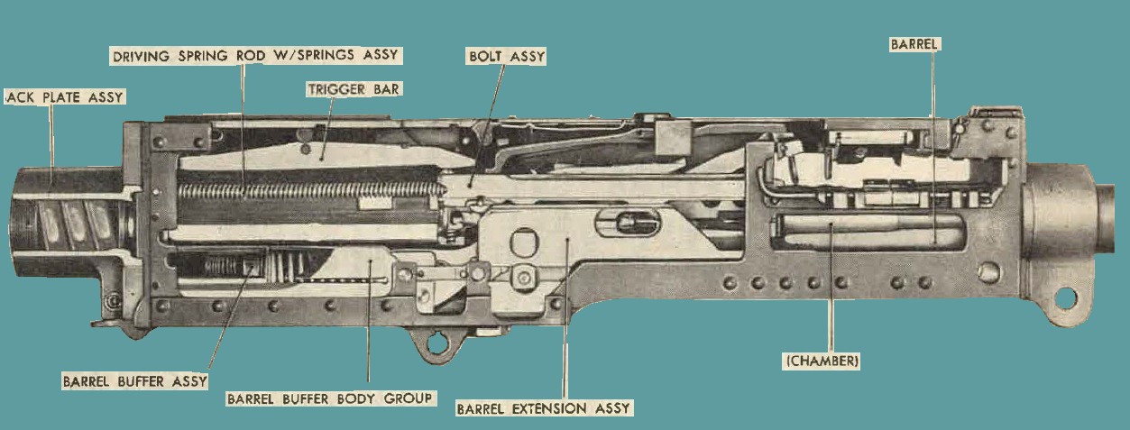
Figure 25. Receiver section of gun - Cutaway view.
c. For convenience and clarity, the cycle of operation is divided into the following phases and explained in the order indicated:
FIRING
RECOILING
COUNTERRECOILING
COCKING
AUTOMATIC FIRING
FEEDING
EXTRACTING AND EJECTING
42. Firing
a. When the gun has been loaded and th firing pin has been cocked, the firing pin extension is engaged with the sea1. The gun is fired by depressing the sear, which releases the firing pin extension.
b. If the gun is fired by a top plate solenoid and trigger bar, the firing pin extension and firing pin are released by energizing the solenoid. The plunger of the top plate solenoid acts on the trigger bar, which pivots on the trigger bar pin assembly, forcing the front end of the trigger bar down to depress the sear and releasing the firing pin. The firing pin and firing pin extension are driven forward by the compressed firing pin spring.
c. If the gun is fired by a side plate solenoid, the plunger of the solenoid is forced against the sear slide. The sear slide, moving laterally, cams the sear downward to release the firing pin.
43. Recoiling.
a. The complete cycle of recoiling takes place as each cartridge is fired. At the instant the first round is fired, the barrel, barrel extension, and the bolt, known as the recoiling parts, are :fully forward or in the BATTERY position.
b. At this point, the bolt is locked to the barrel extension by the breech lock, which extends up from the barrel extension into a recess in the under side of the bolt. The locking action of the breech lock is performed by the breech lock cam upon which it rides. Figure 26 shows bolt locked to barrel extension.
c. When the cartridge explodes, the force of recoil drives the recoiling parts rearward. During the first five-eights of rearward travel, the breech lock is moved off the breech lock cam step. The breech lock is forced down out of the recess in the bolt by breech lock depressors acting on the breech lock pin assembly. This unlocks the bolt from the barrel extension. Figure 27 shows the beginning of unlocking action.
d. As the recoiling parts continue to the rear, the barrel extension bears against the accelerator to rotate it rearward. The tips of the accelerator strike the lower projection on the bolt and accelerate the motion of the bolt to the rear.
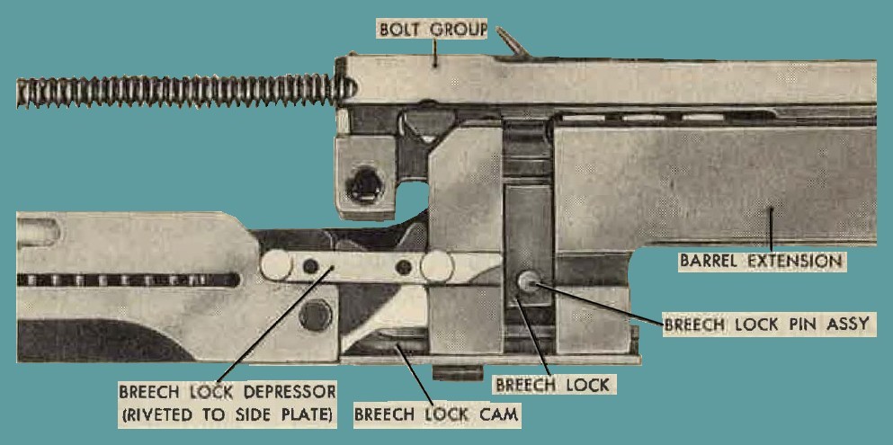
Figure 26. Bolt and barrel extension in locked position.
e. The barrel and barrel extension have a total travel of 11/8 inches at which time they are completely stopped by the barrel buffer body.
f. During this recoil of 11/8 inches, the buffer spring in the barrel buffer is compressed by the barrel extension shank, which is engaged by the barrel buffer piston rod assembly. The spring is held compressed by the claws of the accelerator (fig. 28), which engage the shoulders of the barrel extension shank and lock the barrel extension to the buff er group. The buffer spring assists the banel buffer pist _11 rod assembly in bringing the barrel extension to rest during the recoil movement.
g. During recoil, the barrel buffer piston (fig. 29) is forced rearward in the barrel buffer tube assembly, compressing the air in the tube. The piston starts backward rapidly clue to the air port in the wall of the buffer tube. The port allows air to escape quickly at the
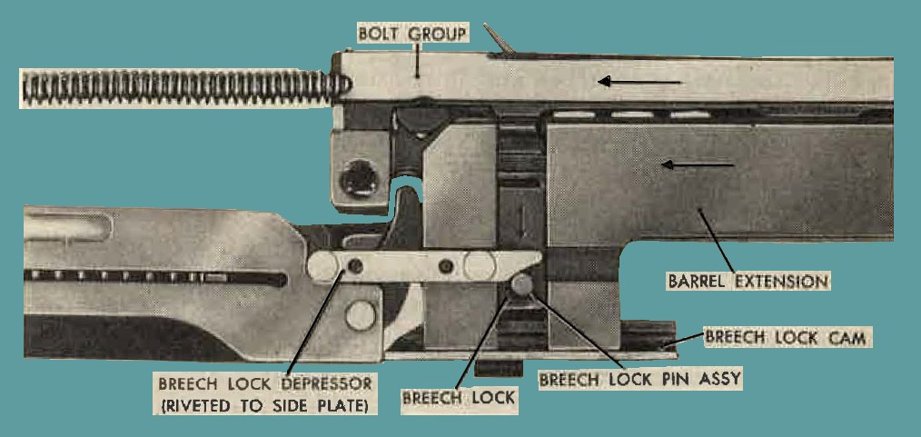
Figure 27. Bolt and barrel extension partially unlocked.
start of the backward movement of the piston. As the piston moves beyond the port, the remaining air in the tube is gradually compressed, forming a cushion. As the compression increases, the compressed air escapes through the spring-operated piston valve. The escaping air passes through the piston and out of the buffer tube through the enlarged rod hole in the tube cap. The valve regulates the flow of escaping air, so that the rearward movement of the barrel extension and barrel is decelerated gradually. The opening of the piston valve is controlled by the valve spring seated in the valve retainer in the piston. The retainer is held in place by the washer springs in the piston. These springs serve as a cushion for the rod at the end of the recoil movement. No terminal shock is transmitted to the piston pin or rod due to the elongation of the piston pinhole in the rod.
h. As the bolt travels rearward, the driving springs are compressed. The movement of the bolt is stopped by the buffer plate in the back-plate.
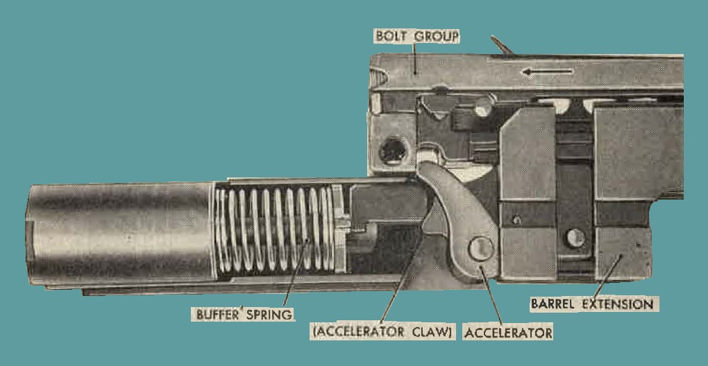
Figure 28. Buffer spring compressed and held by locked barrel extension - bolt still moving rearward.
Part of the recoil energy of the bolt is stored in the driving springs and part is absorbed nnd stored by the cupped washer springs or coil spring upon which the buffer plate bears. Any remaining recoil energy is transmitted to the recoil adapter of the gun or to the gun mountings.
44. Counter recoiling
a. After completion of the recoil movement, the bolt group is forced forward bv the energy stored in the driving springs and the compressed backplate spring. As the bolt (fig. 30). moves forward, the projection on the bottom of the bolt strikes the tips of the accelerator and rotates it forward. This section disengages the claws of the accelerator from the shoulders of the barrel extension shanlr and releases
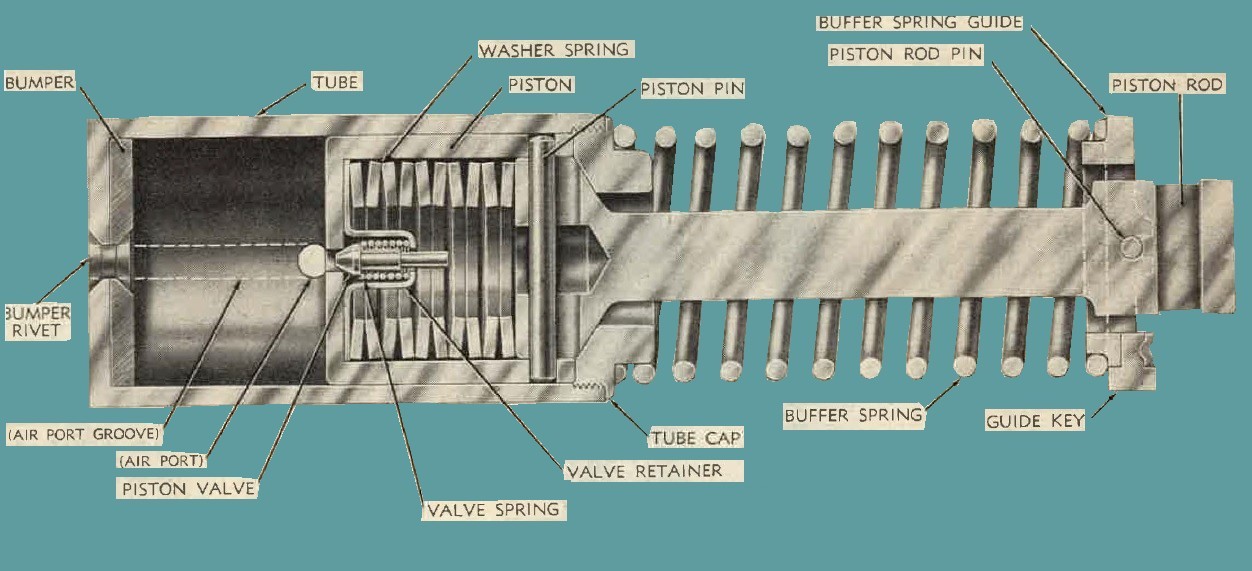
Figure 29. Barrel buffer assembly - Sectional view.
the barrel buffer spring. The expansion of the spring, supplemented by the counterrecoil energy of the bolt transmitted through the accelerator forces the barrel and barrel extension forward.
b. No restriction to the forward motion of the barrel and barrel extension is desired. The air ahead of the piston in the barrel bnffer tube escapes through the enlarged hole in the cap through which the piston rod passes. As the piston nears the forward position, the air ports in the tube is uncovered, allowing air to enter the rear end of the tube and relieve the vacuum created by the forward movement of the piston.
Note. Air is permitted to leave and enter the port in the barrel buffer tube through a longitudinal groove in the tube. This groove extends from the port to the rear of the tube.
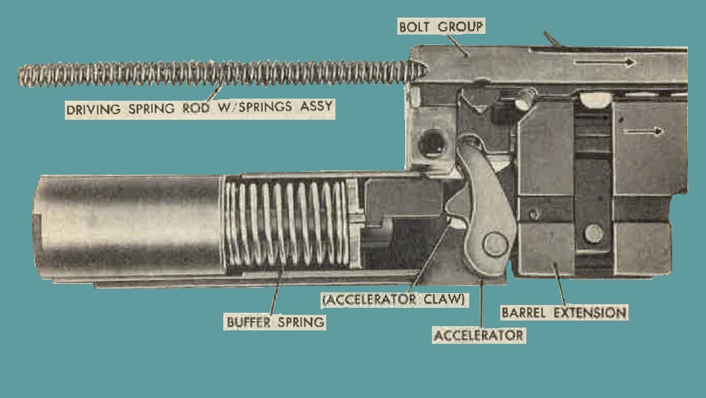
Figure 30. Bolt striking accelerator to release barrel extension and buffer spring.
c. As the barrel extension moves forward, the breech lock rides on the sloping rump of the breech lock cam and is forced upward. The bolt, continuing forward, has at this instant reached a position where the recess in the under side of the bolt is directly above the breech lock. The breech lock enters the recess and engages the bolt. Thus, the bolt is locked to the barrel extension just before the recoiling parts reach the firing position.
45. Cocking.
a. Cocking the gun begins as the bolt starts to recoil. As the bolt moves backward, the tip of the coking 1ever (figures. 31 and 32) is forced forward in the V-slot in the top plate bracket. The coking lever pivots on the cocking lever pin. The lower end of the cocking lever forces the firing pin extension and firing pin backward, compressing the firing pin spring against the firing pin spring stop. The shoulder of the firing pin extension forces the sear downward, against the sear spring, and engages with the notch in the sear. The sear is then immediately forced upward by the sear spring to retain the firing pin extension.
b. During the forward movement of the bolt, the tip of the cocking lever (figs. 33 and 34) again enters the V-slot in the top plate bracket
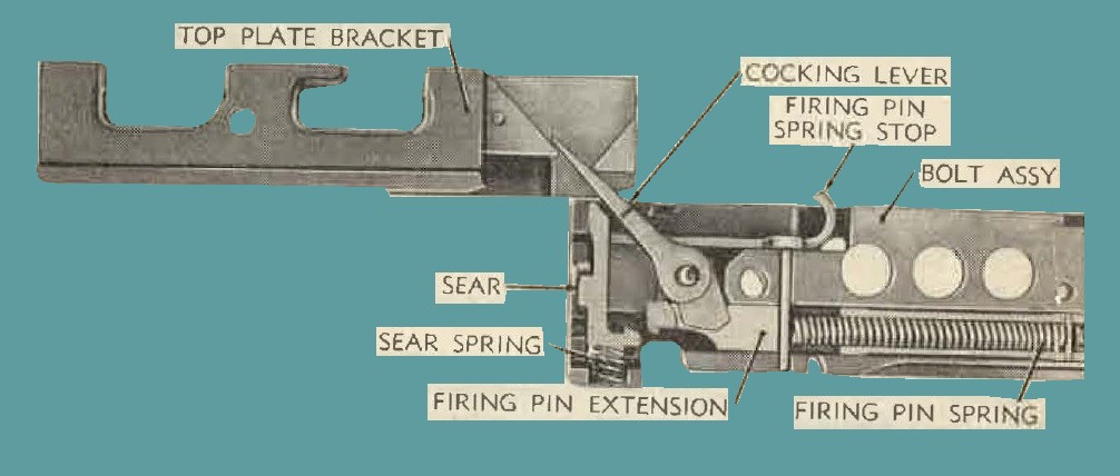
Figure 31. Action of cocking lever during start of recoil.
and is forced backward. This action swings the lower end of the cocking lever forward out of engagement with the firing pin extension. If the firing pin is prematurely released, the cocking lever acts as a safety device, to prevent the pin from moving fully forward to
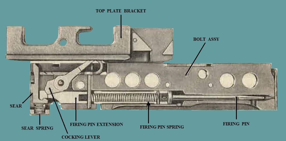
Figure 32. Action of cocking lever during end of recoil.
fire the cartridge until after the breech has been locked. 'When the recoiling parts are 0.116 inch or less from BATTERY, depending on the "timing" of the gun, the gun is ready to fire. If, at this instant, the sear is not depressed, the recoiling parts will assume their fully forward position and the gun ceases to fire.
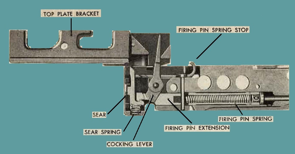
Figure 33. Action of cocking lever during counter recoil.
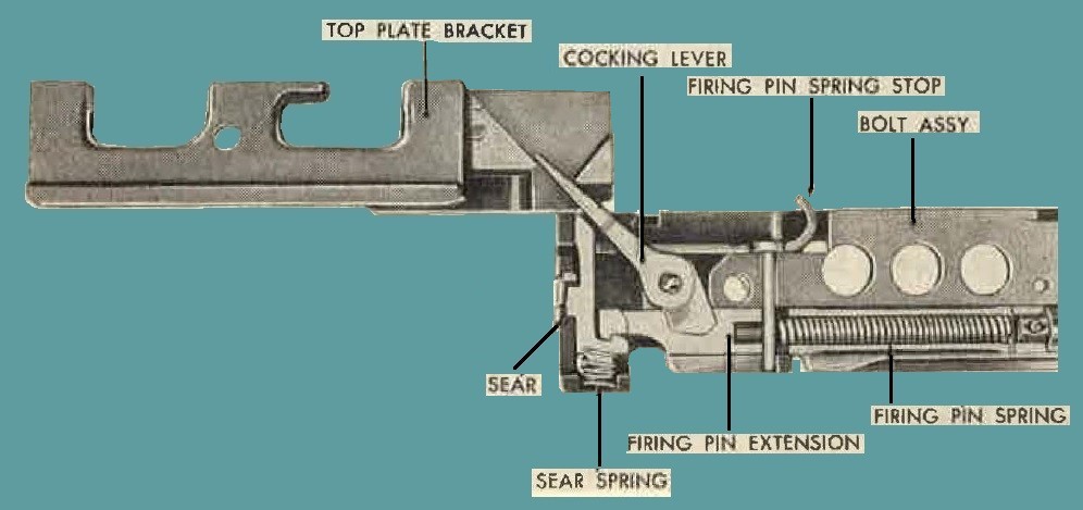
Figure 34. Action of cocking lever at end of counter recoil.
46. Automatic Firing
a. For automatic firing by means of a top plate solenoid, the solenoid must be energized so that its plunger holds the front end of the trigger bar down. As the bolt travels forward on counterrecoil, the sear is depressed when it contacts the trigger bar. The depression of the sear releases the firing pin extension and the firing pin, automatically firing the next cartridge. The gan fires automatically as long as the solenoid is energized or until the ammunition supply is exhausted.
b. Automatic firing by means of a side plate solenoid is accomplished in a similar manner. As the bolt nears the end of its counterrecoil movement, the sear slide strikes the cam surface of the projecting solenoid plunger and is forced sideways. This lateral movement of the sear slide cams the sear downward, thus releasing the firing pin extension and firing pin to fire the gun as outlined in a above.
47. Feeding.
a. The belt feed mechanism is actuated by the bolt. When the bolt is in the forward position, the belt feed slide is entirely within the gun (A, fig. 35). A lug on the rear end of the belt feed lever rides in the diagonal cam groove in the top of bolt. The forward end of the belt feed lever engages a slot in the belt feed slide, to which the belt feed pawl and belt feed pawl arm are attached.
b. When the bolt retracts, the belt feed lever is pivoted on the belt feed lever pivot stud, and the forward end of the lever moves the slide out of the gun over the ammunition belt. The belt is held in position by the belt holding pawl.
c. When the bolt moves forward, the belt feed lever is pivoted and brings the belt feed slide into the gun. The belt feed pawl and arm attached to the slide engage the next round in the ammunition belt and pull the belt into the gun. The belt feed pawl pulls the belt into the feedway against the cartridge stops of the link chute adapter. At this position, the claw of the extractor engages the rim of the cartridge. The belt holding pawl is raised by its spring, behind a link
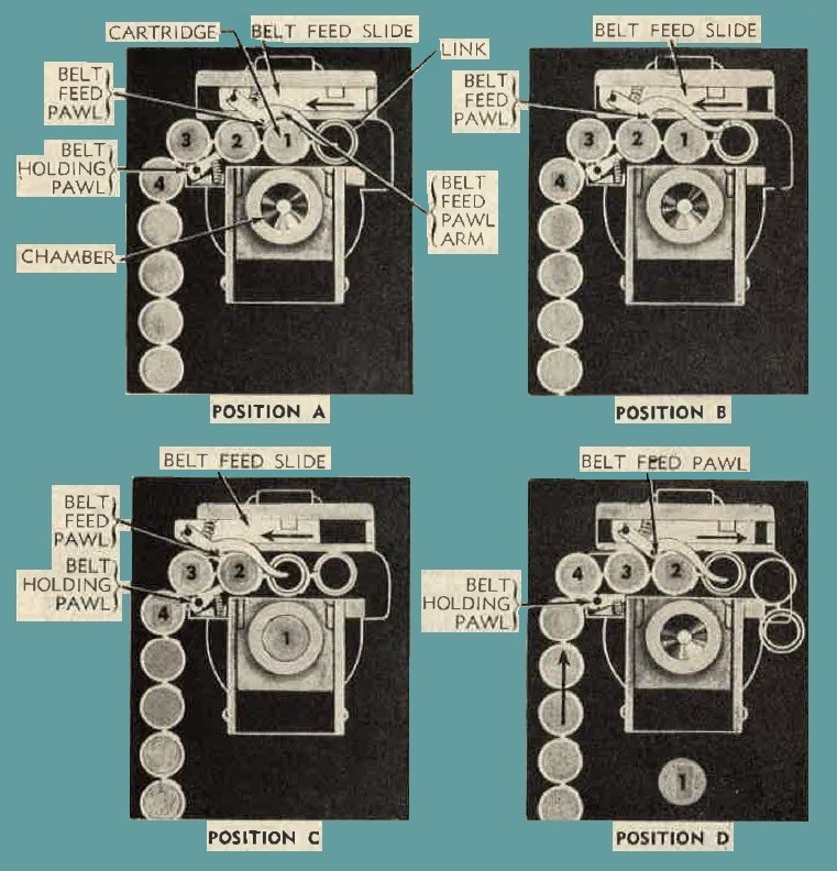
Figure 35. Cycle of feeding, showing position of belt feed and holding pawls.
of the ammunition belt, to prevent the belt from falling out of the gun (A, fig. 35). Feeding during recoil and counterrecoil is outlined in (1) through (3) below.
(1) As the bolt recoils, the extractor withdraws the cartridge from the belt, the belt feed slide is moved out over the belt, and the belt feed pawl rides over the link holding the next cartridge in the belt (B, fig. 35).
(2) At the encl of the recoil movement, the outward travel of the belt feed slide is sufficient to permit the belt feed pawl to snap clown behind the link holding the next cartridge to pull the belt into the gun. (The chambered cartridge in C, figure 35, has been extracted from the belt.)
(3) As the bolt moves forward in counterrecoil, the belt is pulled into the gun by the belt feed pawl. The belt holding pawl is forced clown as the belt is pulled over it (D, fig. 35). As the cartridge is positioned in the feeclw n,y, the belt holding pawl snaps up behind the link holding the next cartridge to keep the belt from falling out of the gun (A, fig. 35).
Note. If the cartridge in the feedway awaiting extraction from the belt fails to be extracted as the belt feed slide starts moving out to engage and pull the belt into the gun, the belt feed pawl arm attachecl to the pawl rides over this unextracted cartridge and lifts the pawl so that it cannot engage the belt. This prevent double feeding.
48. Extracting and Ejecting
a. As recoil starts, a cartridge (fig. 36) is drawn from the ammunition belt by the extractor and the empty case is withdrawn from the chamber by the T-slot of the bolt. The empty case, having been expanded by the force of the explosion, fits the chamber very tightly and the possibility exists of tearing the case if the withdrawal is too rapid. To prevent this and to insure slow initial withdrawal, the top front end of the breeoh lock and the front side of the recess in the bolt are beveled. Thus, before the bolt is completely unlocked, it has moved slightly away from the rear end of the barrel in a gradual manner.
b. As the bolt moves to the rear, the cover extractor cam forces the extractor down, causing the cartridge to enter the T-slot in the bolt.
c. As the extractor is forced down, a lug on the side of the extractor rides on top of the extractor switch (side plate) on the side plate. The switch pivots down as the bolt continues to the rear, until the lug on the extractor clears the end of the switch. As the lug clears the switch, it snaps up to its normal position.
d. On counterrecoil, the extractor is forced farther clown by the extractor lug riding under the extractor switch (side plate). This alines the live cartridge in the T-slot with the chamber. The live cartridge held by the extractor ejects the empty cartridge case from the T-slot. The extractor stop lug on the side of the bolt limits the
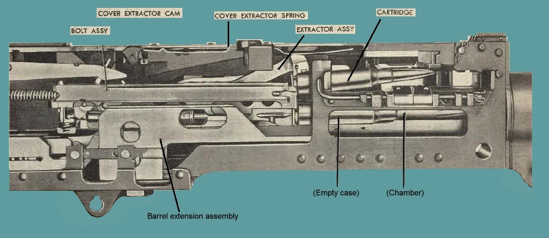
Figure 36. Extracting cartridge from belt and empty case from chamber.
downward travel of the extractor, so that the cartridge, guided by the ejector, enters the chamber of the barrel. When the cartridge is partly chambered, the extractor rides up the extractor cam on the side plate, compresses the cover extractor spring, and is forced down into the extractor groove of the next cartridge in the belt.
Note. The empty case of the last cartridge fired is forced out of the T-slot by the ejector.
49. General.
It is important that the gun and all its equipment be properly installed and maintained. Proper care of the gun and proper preventive maintenance (pars. 35-40) will greatly reduce the possibility of gun stoppages due to malfunctions. When trouble develops, equipment should be carefully checked before assuming the gun itself is responsible for the stoppage.
50. Malfunctions of Gun.
Most of the common malfunctions fall mto the several categories listed in table III.
Table III. Troubleshooting - Organizational Maintenance.
| MALFUNCTION | PROBABLE CAUSES | CORRECTIVE ACTION |
| Double feed - Interference of belt feed pawl with ammunition links. | The corner of the belt feed pawl catches the web between the single and double loop of the ammunition links when feeding from the right side. | Replace with latest belt feed pawl assembly 7265639 (pars. 74 and 76). |
| |
||
| Loose link chute adapter nut. | Fiber inserts used in nuts on some guns deteriorate when subjected to saturation with cleaning solvents and oils. | Replace with nuts with nylon inserts (pars. 78-80). |
| |
||
| Broken barrel extension shank. | Gun firing out of battery due to firing pin retaining pin not being installed during assembly of firing pin and extension assembly. | Correct assembly of firing pin and extension assembly (par. 59b). Replace barrel extension assembly (par. 71c). |
| |
||
| Battered accelerator. | Gun firing out of battery due to firing pin retaining pin not being installed during assembly of firing pin and extension assembly. | Correct assembly of firing pin and extension assembly (par. 59b). Replace accelerator (par. 65a(2)) |
| |
||
| Warped cover. | Gun firing out of battery due to firing pin retaining pin not being installed during assembly of firing pin and extension assembly. | Correct assembly of firing pin and extension assembly (par. 59b). Notify field maintenance personnel. |
| |
||
| Rupture cartridge case. | Gun firing out of battery due to firing pin retaining pin not being installed during assembly of firing pin and extension assembly. | Correct assembly of firing pin and extension assembly (par. 59b). Notify field maintenance personnel. |
| |
||
| Loose head space. | Check and adjust head space (par. 14). | |
| |
||
| Damaged barrel buffer body assembly. | Interference of the barrel buffer body and breech lock depressors. | Notify field maintenance personnel. |
| |
||
| Failure to feed - Gun stops firing in battery position and empty chamber. | Belt feed lever bent or broken due to broken belt feed pawl arm. | Replace belt feed lever and pawl arm (par. 76d and e(2)). |
| |
||
| Failure to fire. | Firing spring weak or broken causing lightly struck primer (figure 37). | Adjust timing (par. 15). Replace the firing pin extension assembly (par. 59c). |
| |
||
| Dirt or excess oil in firing pin extension assembly may congeal at low temperatures causing lightly struck primer (figure 37). | Remove spring (par. 57k) and lubricate (pars. 33 and 34). | |
| |
||
| Defective ammunition. | Charge gun (par 19d). | |
| |
||
| Firing pin fails to release. | Check timing (par. 15) | |
| |
||
| Broken firing pin. | Replace firing pin (par 57j) | |
| |
||
| Failure to feed - gun stops firing with recoiling parts out of battery position. | Broken backplate buffer washer spring. | Notify field maintenance personnel for replacement. |
| |
||
| Link Jam. | Check link chute adapter assembly (par. 79k). | |
| |
||
| Head space too tight. | Check head space (Par. 14). If head space is incorrect, check barrel locking spring for fracture, weakness, or worn projection. Adjust head space (par 14). | |
| |
||
| Breech lock cam too tight, causing binding of barrel extension in guides of the cam. | Check breech lock cam clearance (par. 80d). | |
| |
||
| Ruptured cartridge case. | Check head space (Par. 14) | |
| |

Figure 37. Comparison of normal and light indent in primers.
51. General
a. The backplate assembly inoloses the rear end of the receiver and is mounted in grooves in the receiver side plates. During the cyclic operation of the gun, the rearward moving bolt strikes the buffer plate (fig. 38) . The backplate spring cushions the impact of the bolt and
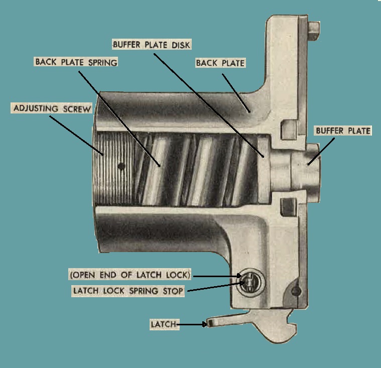
Figure 38. Backplate assembly - Cutaway view.
starts the bolt forward. The backplate assembly also acts as a stop for the barrel buffer group and the driving spring rod with spring assembly.
b. Backplate assemlies of present manufacture have a coil-type backplate spring in place of the buffer washer spring group assembly formerly used.
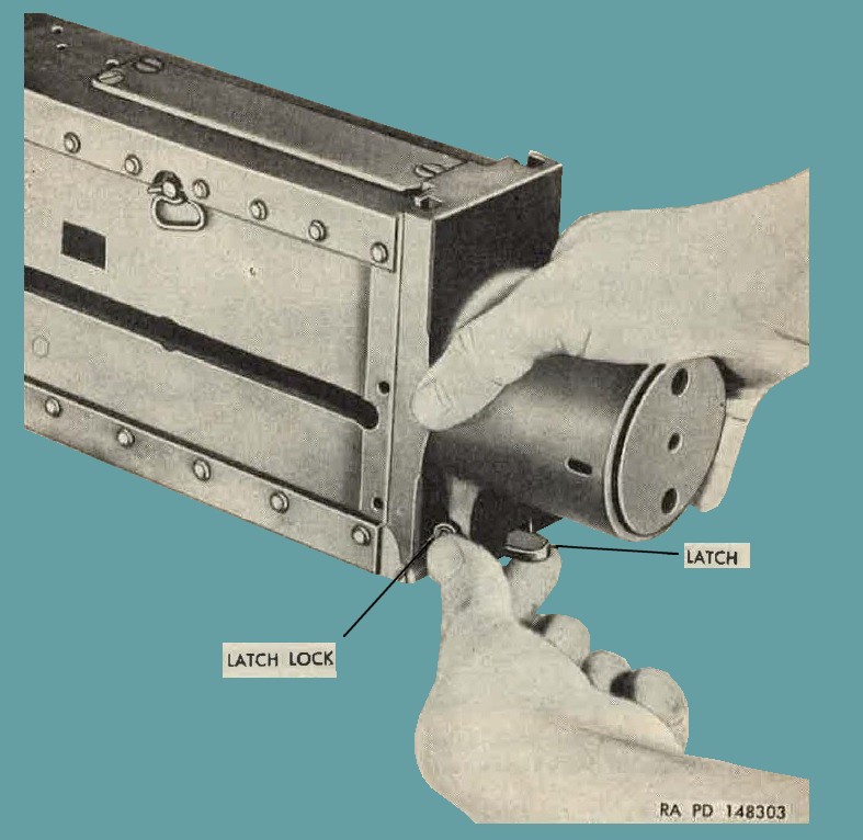
Figure 39. Removing backplate assembly.
52. Removal and Disassembly
Note. Before removing the backplate assembly, make sure that the bolt group ls fully forward.
a. To remove backplate assembly, push in the backplate latch lock (fig. 39) and raise backplate latch. Hold the latch in raised position and slide backplate up until it is free of the receiver.
b. Place backplate assembly in vise.
c. Place adjusting screw plunger depressor tool '7265950 (fig. 40) around backplate and with the studs of the tool depress the adjusting Screw pluger. secure tool on backplate by placing the lock over the extended ends of the tool. Remove adjusting screw, using cal. .50 combination wrench 7161767 (figure 40).
d. Remove adjusting screw plunger (figure 41) and spring from adjusting screw. Push buffer plate and wn.sher springs or hackplate spring from buffer tube.
Note. Keep each set of 10 washer springs tog1•the1·.
e. With tho latch depressed, drive out backplate latch pin with a driftpin. Remove latch and spring. Take care not to lose the spring.
f. Insert the large sp]it end of the cal. .50 oombination assembling and disassembling tool 7265946 (figure 19) into the end of the latch lock
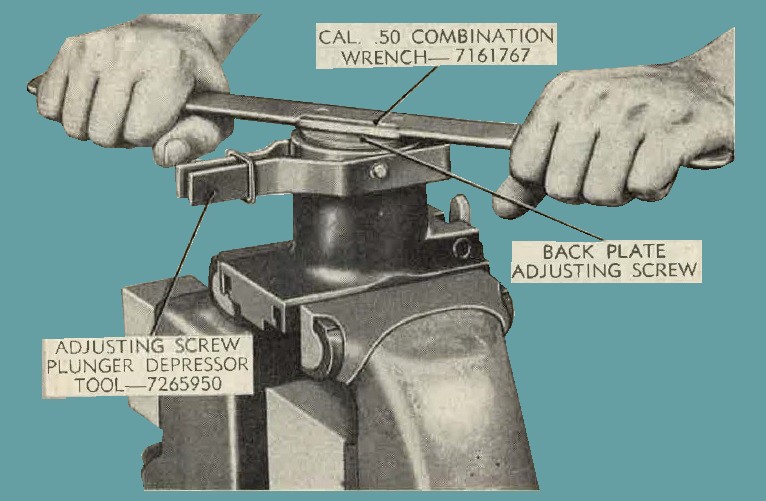
Figure 40. Removing backplate adjusting screw, using cal. .50 combination wrench 7161767 and adjusting screw plunger depressor tool 7265950.
with the ends of tool straddling the latch lock spring stop. Compress the latch lock spring with the tool and remove the latch lock spring stop. Remove latch lock and latch lock spring.
53. Maintenance
a. Check AF Form 185 for rounds fired. Inspect buffer washer springs or backplate spring every 1,000 rounds.
b. Replace latch lock spring, latch spring, or adjusting screw plunger spring if weak, kinked, or broken.
c. Replace latch lock spring stop or latch pin if bent.
d. Inspect backplate spring or washer spring group assembly for cracks, fractures, and burs. An unserviceable washer spring necessitates
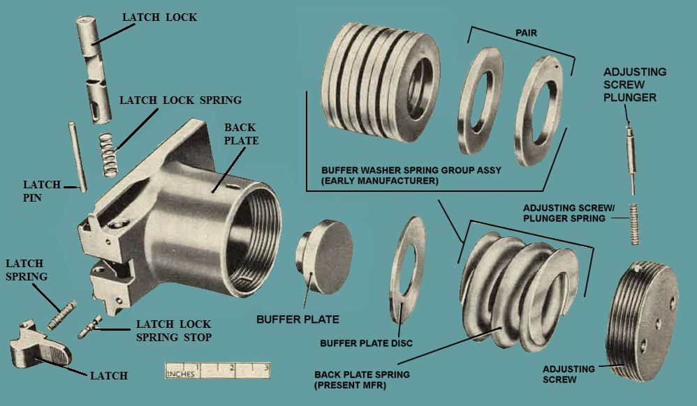
Figure 41. Backplate assembly - exploded view.
replacement of the entire set; if replacement is necessary, notify field maintenance personnel.
e. Wipe all parts dry and apply a light film of oil.
54. Assembly and Installation.
a. Place latch lock spring (figure 41) in open end of latch hook. Insert lock (spring leading and center notch down) into transverse tunnel of backplate. Assembly can be performed on either left or right side.
b. Aline latch lock slots in position, with latch lock spring stop hole in bottom of backplate and insert spring stop. Still holding lock compress spring with the cal .5o combination assembling and disasembling t00l 7265046 (figure 19) and push stop)all the way in. Stop should be retained by the spring positioned over the center raised portion.
c. Place latch spring in its seat in the latch, aline pinholes in latch and backpfato, and push in latch pin until flush with surfaces of backplate. When assembled, operate latch and lock to make sure they function properly.
d. Insert buffer plate into the tube portion of backlate with small diameter foward. If washer spring type insert the 10 cup-shaped, washer springs into the buffer tube. Insert springs (Figure 41), in pairs, so that the cupped faces of each pair are facing each other. If coil spring type, insert buffer plate, disk and backplate spring (figure 41). Thread the adjusting screw in a backplate until hole for adjusting screw plunger and spring is not quite flush with end of tube. Insert plunger spring and plunger into hole in the adjusting screw. Deress plunger and screw the adjusting screw into the backplate until the plunger is held compressed in the tube. Grasp the portion of the buffer plate that projects through the front of the backplate with the fingers and slighhly rotate the buffer plate back nnd forth. At the same time, tighten the adjusting screw, using the Cal. .50 combination wrench 7161767, until the buffer plate can no longer be moved with the fingers. After this point is found, tighten the adjusting screw to the next plunger click. Depress the plunger and take an additional turn. This results in an adjustment of 1 to 1½ turns of the adjusting screw after the buffer plate is no longer free to turn. Be sure the plunger is engaged in its lock slot.
Note. Be sure plunger is disengaged from slot in buffer before attempting to turn the adjusting screw. When tightening the adjusting screw, the backplate should be held in a vise. Do not tighten the adjusting screw while backplate is assambled to receiver except in an emergency.
e. Start the backplate assembly into its grooves in the rear end of the rceiver side plates. Push in latch lock, raise latch, and push the backplate assembly down as far as it will go. Release latch and lock. Check to see that backplate assembly is secure.
55. General.
a. The bolt group is the major recoiling part of the weapon. During the firing cycle, the bolt group acts to cock the firing pin, extract and eject the cartridge case, chamber a new cartridge, and actuate
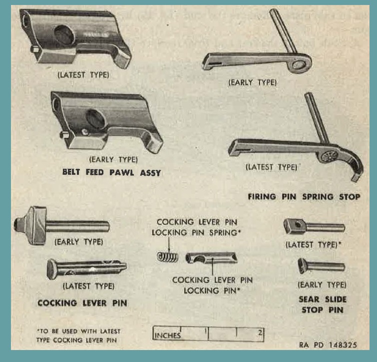
Fiugre 42. Comparison of early and latest parts for gun AN-M3.
the belt feed lever in order to advance the ammunition belt. See paragraphs 42 through 48 for additional explanation of the operation of the weapon.
b. In order to change the weapon from right- to left-hand firing, certain parts of the bolt group must be repositioned (par. 16).
c. Two bolts are presently in use. These bolts differ only as to the cocking lever pin (figure 42). Bolts of present manufacture (modified) have a well (figure 43) drilled in the top surface to accommodate the cocking lever pin locking pin spring and pin.
a. Remove backplate ass@1bly (par. 52).
b. Remove driving spring rod with springs assembly (Figure 44) by pressing forward and away from the right side plate, to disengage the retaining pin of the rod from its hole in the side plate. It is then free to withdraw rod with springs assembly from the gun. Take care not to bend rod while performing this operation.
c. Retract bolt until the bolt stud is in line with enlarged hole in slot in side plate. Remove the stud (figure 45) by pulling it out to the side.
d. Slide bolt to the rear and from receivcr (figure 46).
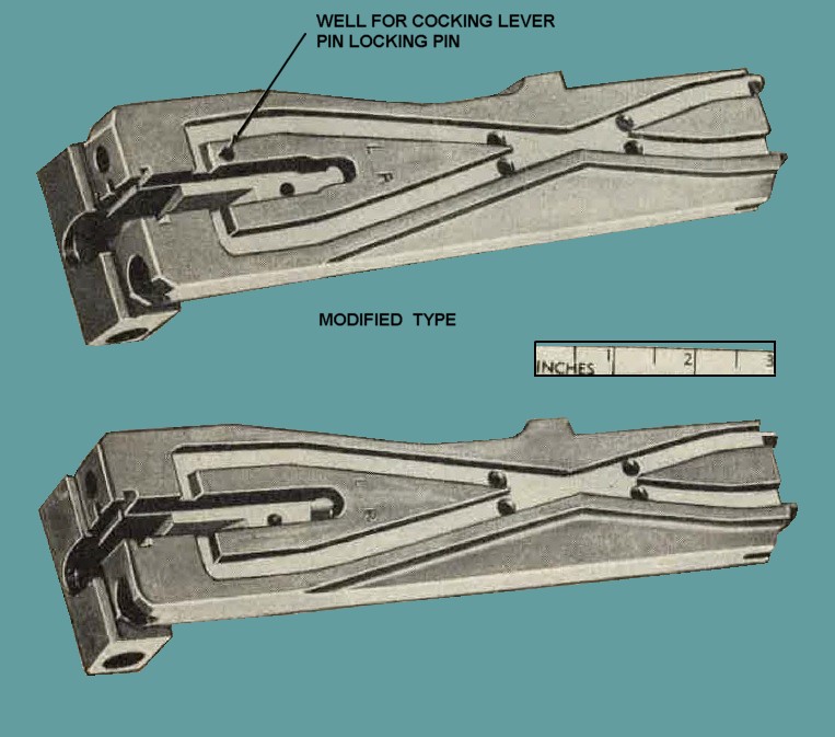
Figure 43. Comparison of bolts.
57. Disassembly
a. Remove the extractor assembly (figure 10) by rotating it upwards to a vertical position and pulling it from the side of the bolt.
b. To remove ejector (figure 11) from extractor assembly, depress spring-loaded ejector pin retainer and push out the ejector pin with a drift. Be careful ejector and spring do not fly out when pin is removed.
Note. The ejector pin retainer is locked in place by the retainer locking pin, and disassembly is not authorized by organizational personnel.
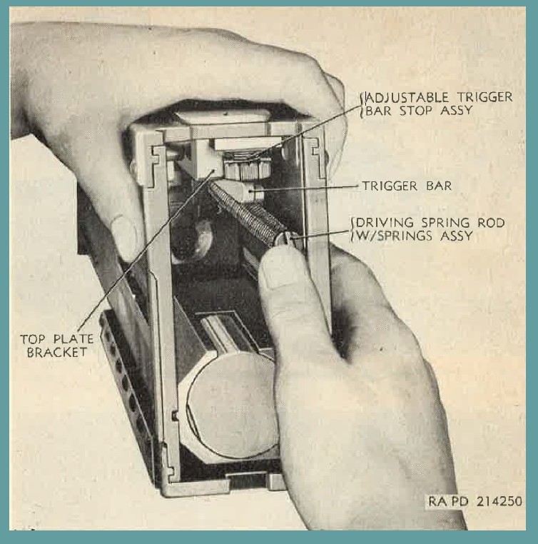
Fiugre 44. Removing driving spring rod with springs assembly.
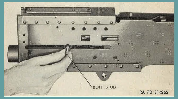
Fiugre 45. Removing bolt stud.
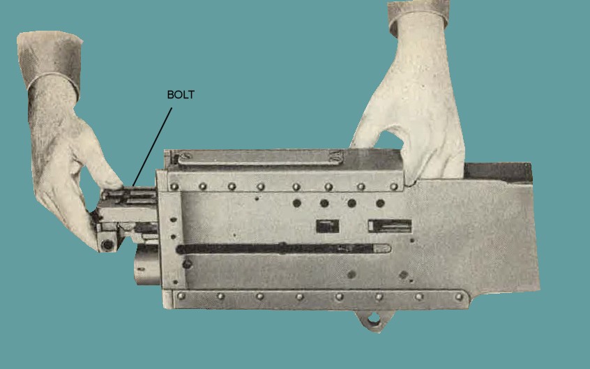
Fiugre 46. Removing bolt group from receiver.
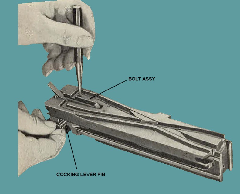
Fiugre 47. Removing cocking lever pin.
c. Rotate cocking lever fully backward and release the firing pin by pushing down on the sear.
Caution: Do not attempt to release the firing pin with cocking lever forward, as the lever will spring back forcibly and may cause serious injury.
d. To remove the cocking lever pin (figure 47) from present design (modified) bolts, press clown on the cocking lever pin locking pin with a driftpin and withdraw the cocking lever pin. Remove locking pin and spring.
e. On present design bolts, it is only necessary to push out cocking lever pin from bolt.
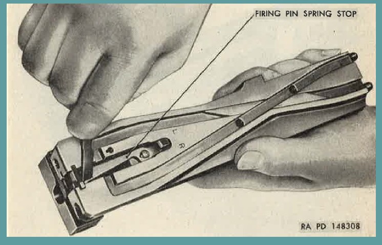
Fiugre 48. Disengaging firing pin spring stop.
f. Remove cocking lever.
g. Using the thin end of the cocking lever, engage the groove in the firing pin spring stop (figure 48) and swing the stop laterally from its Peating groove. Push the stop from under side of bolt or pry up under the curved portion of stop and withdraw it from the bolt.
h. Press clown on sear, push out the sear slide stop pin ( fig. 49), and withdraw sear slide.
i. Remove sear and sear spring (figure 50) by raising them up and free of bolt.
j. Elevate front end of bolt and allow firing pin extension assembly and firing pin to slide out. Disengage firing pin from firing pin extension assembly by removing firing pin retaining pin.
k. Disassemble firing pin extension assembly, using the cal. .50 firing pin spring removing tool 6243646 (figures. 17 and 51). To disassemble extension assembly, clamp it lightly but firmly in a vise. Engage head of tool tube with end of extension, so that slot in rod straddles firing pin spring stop pin. Compress the spring aud push out stop pin. The small split emnd of the cal. .50 combination assembling and disassembling tool 7265946 (figure 19) can be used to perform tit sn,m:e operation.
l. To remove bolt switches, drive out bolt switch locking pins, and lift out switches (figures. 52 and 53).
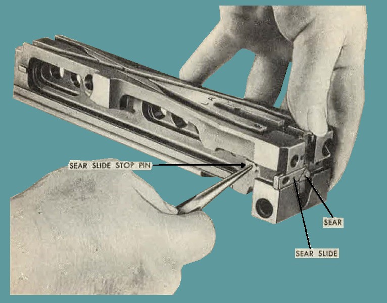
Fiugre 49. Removing sear slide stop pin.
58. Maintenance
a. Check AF Form 185. See inspection and rebuild schedules (par 37) and make inspection at 5,000 and 10,0OO rounds. Firing pin, firing pin extension assembly, sear, sear slide, sear spring, cocking 1ever pin, firing pin spring stop, firing spring stop, firing pin retaining pin, ejector pin and alternate feed bolt switch locking pins should be carefully inspected.
b. Inspect bolt group components frequently for signs of rust, corrosion, and wear; replace if necessary.
c. A11 bolt assemblies should be checked for cracks in the rear face. of the bolt; replace if defective.
d. Remove any rust or burs from the bolt, using crocus cloth or a fine grain sharpening stone. Clean all recesses and tunnels of foreign matter, grease, or excess oil. Scrape or use crocus cloth to remove any accumulated carbon from T-slot. Clean firing pinhole, using caliber .50 firing pinhole cleaning brush 7162702 (figure 15) and caliber .45 cleaning rod M4-55G4102 (fig. 1G).
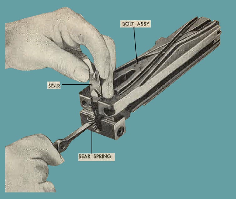
Fiugre 50. Removing ot assembling sear and sear spring.
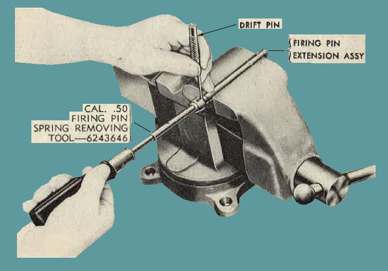
Fiugre 51. Disassembling firing pin extension assembly, using cal. .50 firing pin spring removing tool 6243646.
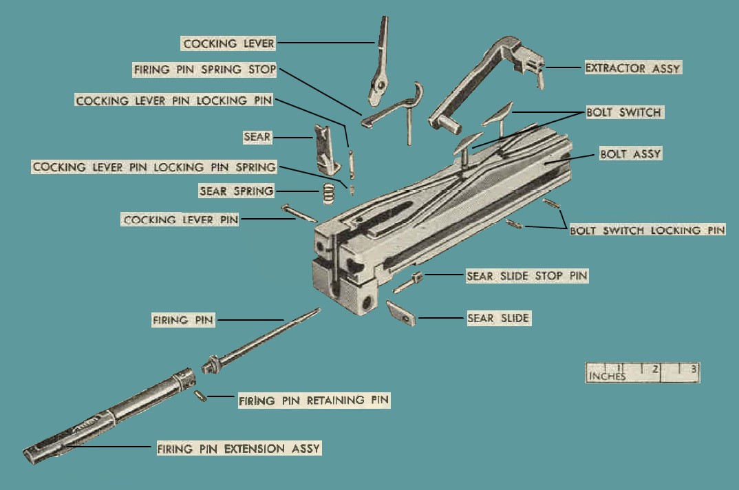
Figure 52. Present design (modified) bolt group - exploded view.
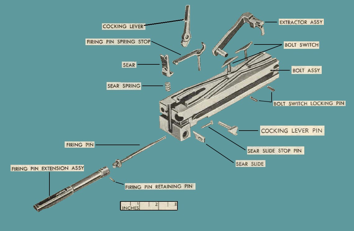
Figure 53. Present design bolt group - exploded view.
e. Be sure driving spring rod is not bent and that inner and outer driving springs operate freely. Check retaining pin for looseness and wear; replace if necessary.
f. Sear springs having six coils will be replaced by springs with four coils.
g. Check to see that extractor stop lug on left si(le of bolt is not worn, burred, or broken.
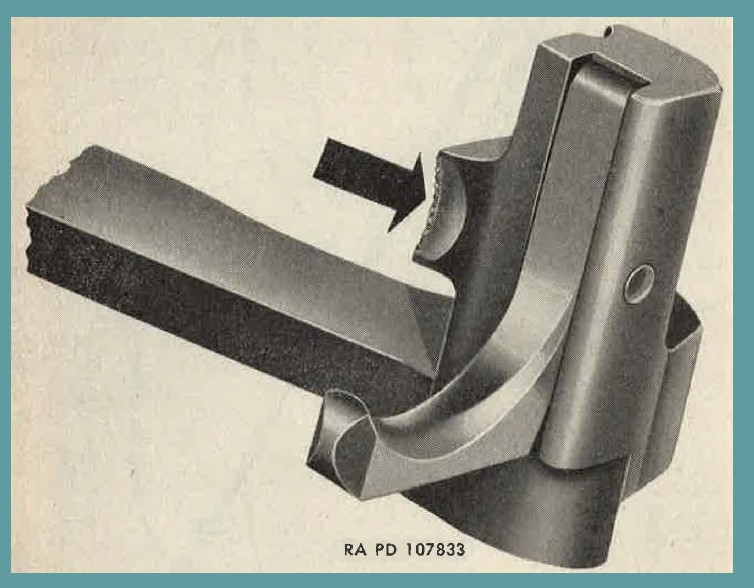
Figure 54. Worn extractor.
h. Check tear-drop lug on extrndor for excessive battering, and check to see that extracting lip is not worn (Figure 54).
i. See that bolt stud does not bind in slot in side plate when assembled. Replace reversible-type bolt studs with nonreversible-type.
59. Assembly
a. Insert bolt switches (figures. 52 and 53) in holes in groove, so that groove marked R is continuous if right-hand feed is desired, and vice versa if left-hand feed is desired. Install bolt switch Jocking pins.
b. Place the firing pin spring in the firing pin extension. Position the head of cal. .50 firing pin spring removing tool 6243646 (figure 51) over end of extension, with slot in tool head stradling holes in extension. Compress spring and install the firing pin spring stop pin.
c. Assemble firing pin to firing pin extension assembly and insert firing pin retaining pin. Insert them into tunnel of bolt with the notch of the firing pin extension down. Push the extension all the way forward, so that the tip of the firing pin protrudes from the face of the bolt.
d. Insert sear spring (figure 50) into its well in the bolt. Place the sear in the vertical grooves with the wedge-shaped surface facing outward and pointing upward. Press the sear clown on the spring, to be sure that the spring is seated properly with lug on bottom of sear inside coils of spring.
e. Insert sear slide into its lateral guideway so that the sloping cam contacts the cam on sear. Depress sear slightly and push the slide until the elongated slot in the slide alines with sear slide stop pin hole in bolt. Retain the sear slide (figure 49) in position by inserting the stop pin, so that its head faces toward the front of the bolt and the flat side is against the side of the bolt.
Note. If the gun is to be fired by a side plate solenoid, the slide must Le inserted so that the square end is on the same side of the bolt as the solenoid is mounted.
f. Insert the firing pin spring stop in its aperture. Swing the stop (fig. 48) in its groove, using the tip of the cocking lever.
Note. Be sure the firing pin protrudes beyond the front face of the bolt before assembling firing pin spring stop.
g. Insert cocking lever pin locking pin spring and pin in hole on top of bolt in bolts of present design (modified) ( fig. 52).
h. Insert cockrng lever (fig. 55) into slot in top of bolt, with the rounded nose on the lower encl of lever to the rear and the shoulder on the side of the lever to the right; insert cocking lever pin as far as it will go. Depress locking pin and push the cocking lever pin in all the way.
Note. The tail of the cocking lever pin retains the sear slide stop pin in position; therefore, the cocking leYer pin must be inserted from the sicle opposite to that from which the sear slide is assembled.
i. Push cocking lever forward all the way, retnrn it fully to its rear position, and press clown on the sear. A sharp metallic sound heard when the firing pin is released will indicate that the assembly of bolt group is correct and in good "·orking order. Push the cocking lever forward all the ,my before installing bolt group into gun.
Caution: Do not attempt to release the firing pin with cocking lever forward, as it will spring back forcibly and may cause serious injury.
j. I£ the gun is to be assembled for left-hand feed, the ejector (fig. 12) should be assembled with the claw to the right side of the extractor; for right-hand feed, the ejector should be assembled with the claw to the left side of the extractor, when viewed from the rear. Assemble ejector as described in (1) through (3) below.
(1) Insert the ejector spring in its recess in the extractor and position the ejector over the spring (fig.11).
(2) Aline the pinhole in the ejector and extractor and insert the ejector pin from the rear. The flat of the ejector pin must face the ejector pin retainer in the extractor. Press in on the spring-loaded retainer with a driftpin, so that the ejector pin will fully seat. Release the retainer to lock pin in position. Check to see that pin is fully seated and locked. Check spring action of ejector.
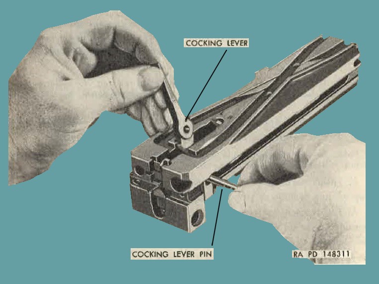
Fiugre 55. Assembling cocking lever and cocking lever pin.
(3) with the extractor assembly (fig. 10) in a vertical position, insert the pivot into the bolt and rotate it forward. Make sure the flange on the bottom of the extractor engages behind the shoulder on the bolt, locking it in position. Do not force assembly.
60. Installation.
a. Push the barrel and barrel extension far enough to the rear so that the breech lock does not interfere with the entrance of the bolt group.
b. With the. cocking lever rotated fully forward, slide tho bolt group into receiver and engage it with the guideways in the barrel extension. Take care when inserting the bolt group not to trip the accelerator forward, and be sure the tip of the, cocking lever is under the top plate bracket, before pushing the bolt group forward. The front end of the bolt should be lifted over the tips of the accelerator to facilitate assembly.
c. Push the bolt group forward, until the hole for the bolt stud is in alinement with the enlarged opening in the center of the slot in the side plate, and insert bolt stud.
d. Insert the driving spring rod with springs assembly into its hole in the bolt, and push the bolt group completely forward.
e. Compress the driving springs slightly by pushing forward on the head of the driving spring rod, and engage the driving spring rod retaining pin in the hole in the right side plate.
f. Press head of rod flat against side plate. Caution: Do not use the driving spring rod with springs assembly as a lever or auide for the bolt group when inserting the group in the receiver, as his may bend the rod. Be sure that the rod is straight and the outer driving spring does not rub excessively or bind in its tunnel in bolt.
g. Install backplate assembly (par. 54e). Be sure head of driving spring rod is flat against side plate and pin fully engagcd in hole, so that head will seat in groove of backplate.
61. General.
a. The barrel buffer group (figure 3) is composed of the barrel buffer body group and the barrel buffer assembly (figure 58). When assembled, the buffer assembly is housed in the buffer body.
b. The barrel buffer group has four main functions: to bring the barrel and barrel extension group to rest, cushioning the shock, and holding them on recoil; to transmit recoil energy of the barrel and barrel extension through the accelerator, to speed up the recoil of the bolt; to return the barrel and barrel extension to battery by means of the expanding buffer spring assisted by the accelerator on counterrecoil; and by means of the accelerator, to coordinate the locking action of the barrel extension and bolt. Detailed functioning of the components of the barrel buffer group is explaiiied in paragraphs 42 through 48.
62. Removal.
a. Remove uackplate assembly (par. 62) and bolt group (par. 56).
b. Insert a driftpin or other suitable tool in the hole (figure 56) near the rear of the right side plate and depress barrel buff er spring lock. At the same time, push the barrel and barrel extension group and barrel.
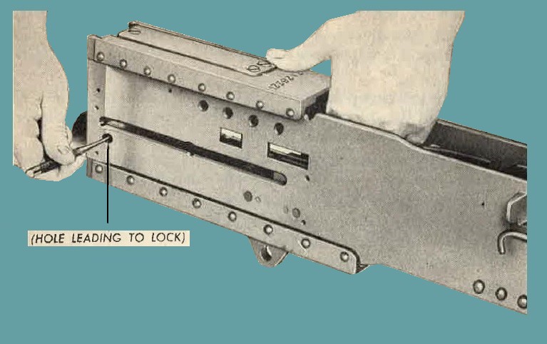
Fiugre 56. Disengaging barrel buffer body spring lock.
buffer group to the rear. When the barrel buffer group (figure 57) clears the rear of receiver, it can be disconnected from the banel extension by pushing forward on the tips of the accelerator.
Note. Should these guns be mounted so closely together that the barrel buffer body svring lock cannot be released by a clrift11iu in the conventional manner, place support of cal. .30 buffer spring lock relaese tool 71G1SlG (figure 17) against rear face of right side plate. Apply point of rod into hole nenr the right side plate aml depress the banel buffer body spring lock.
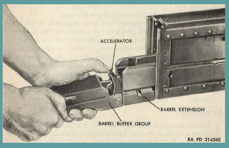
Fiugre 57. Removing barrel buffer group.
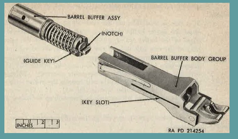
Fiugre 58. Barrel buffer group - Exploded view.
63. Disassembly.
a. Push the barrel buffer assembly (fig. 58) out of the rear end of the barrel buffer body group.
b. Disassembly of barrel buffer body group is described in (1) and (2) below.
(1) Push out the accelerator pin and remove accelerator (figure 59)
(2) If necessary to remove barrel buffer body spring lock, remove staking and drive ont of slot.
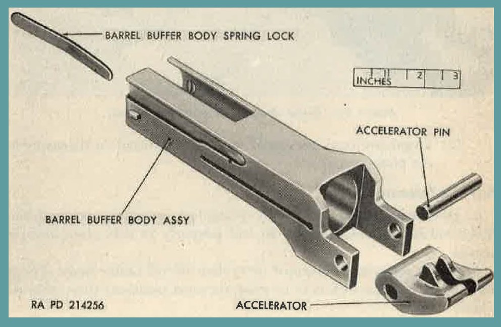
Fiugre 59. Barrel buffer body group - Exploded view.
c. Disassembly of barrel buffer assembly is described in (1) and (2) below.
(1) If a vise is available, set the jaws a.bout 11/8 inches apart. Hold the barrel buffer firmly in both hands and place the edges of the buffer spring guide assembly against the open jaws of the vise (figure 60). Press forward on the banel buffer tube to compress the buffer spring. Turn the buffer one quarter turn in either direction to aline the piston rod pin with the slots in the buffer spring guide assembly. Release the pressure on the tube slowly and remove the buffer spring guide assembly and buffer spring (Figure 61). If a rise is not available, the buffer spring may be rermoved as indicated in figure 62.
Caution: Use great care in removing the buffer spring, as it is highly compressed.
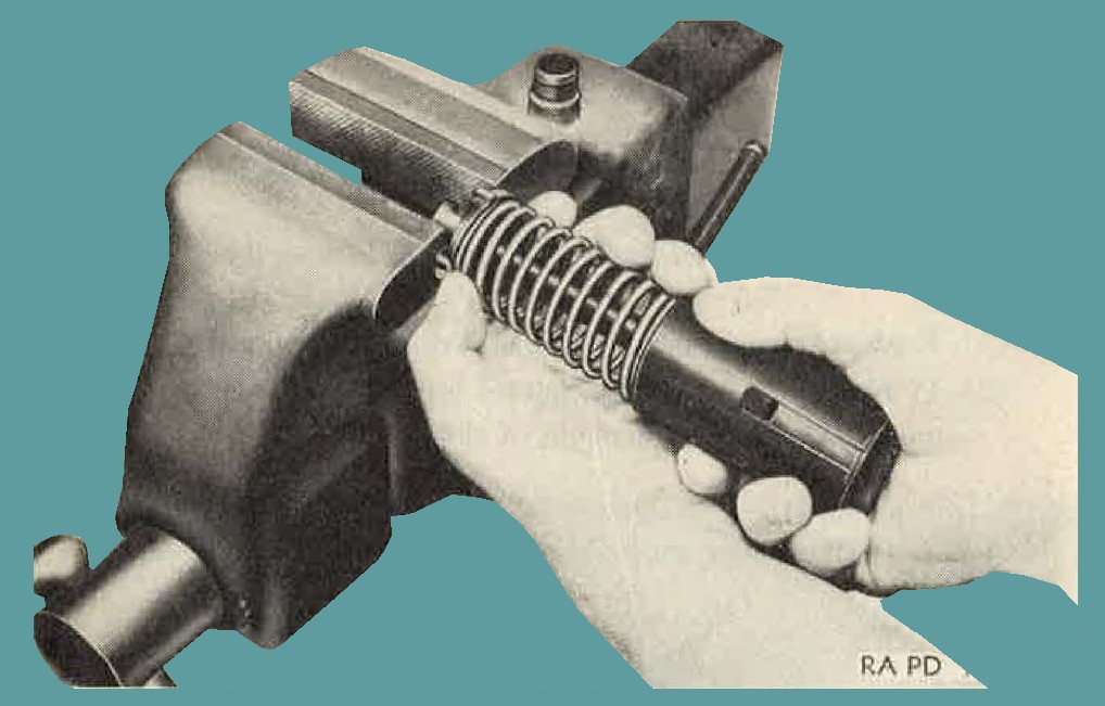
Fiugre 60. Using vise to remove buffer spring.
(2) Organizational personnel are not permitted to disassemble the piston group.
64. Maintenance.
a. Be sure the barrel buffer body spring lock is staked securely in the body and has suifficient spring to seat properly in side plate locking recess.
b. When replacing deformed or broken barrel buffer body spring lock, be certain the lock is in its most forward positiou then stake in place.
Note. Do not overstake.
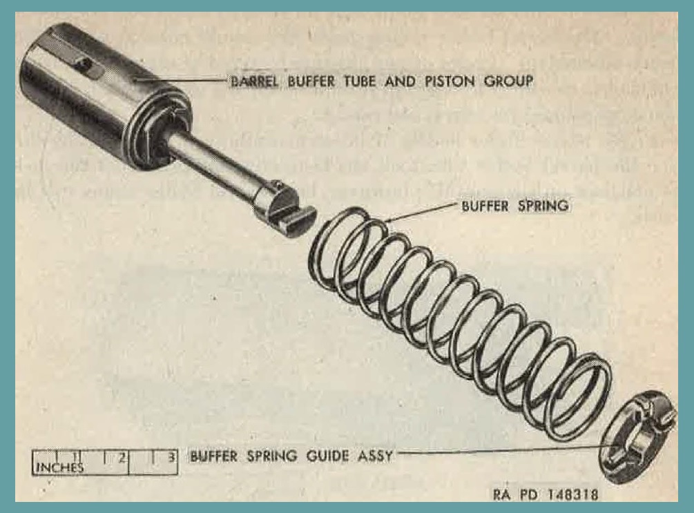
Fiugre 61. Barrel buffer assembly - Partial exploded view.
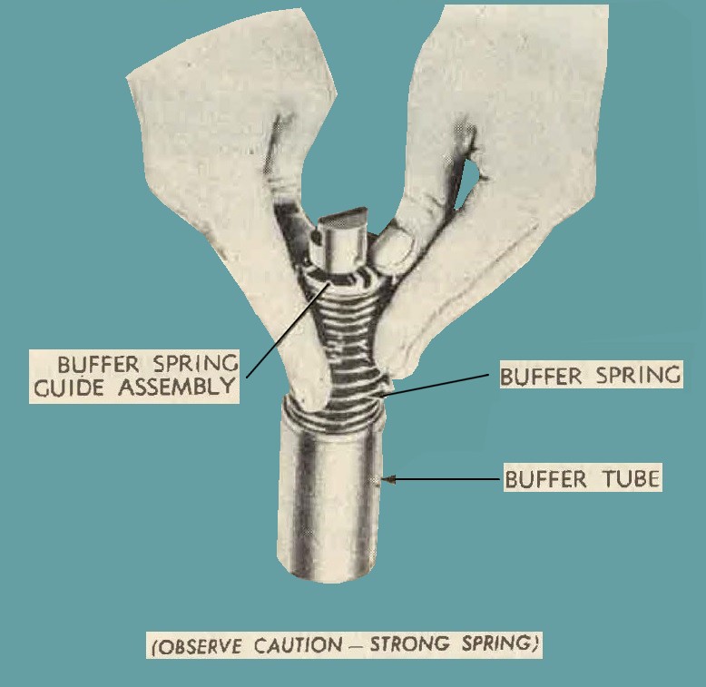
Fiugre 62. Removing buffer spring without use of vise.
c. Remove any burs on guide lugs on sides of body and key slot in body. The barrel buffer spring guide key should move freely in slot when assembled. If slot or key appenrs battered or worn, it indicates the slot is too short and group should be turned over to field maintenance personnel for check and repair.
d. On barrel buffer bodies of latest manufacture (fig. 63), the slot for the barrel buffer tube lock has been eliminated because the lock is not used on the gun M3; however, both barrel buffer bodies can be used.
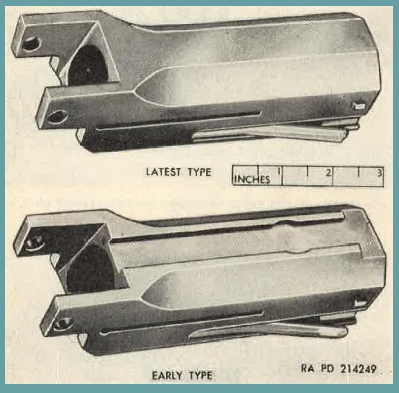
Fiugre 63. Comparison of barrel buffer body assemblies.
e. Remove any burs on the accelerator or accelerator pin. Inspect the accelerator for chipping or wear. See figure 64 for a comparison of early and latest accelerators.
f. Check barrel buff er spring for cracks or rust; check key on spring guide for looseness, wear, or burs.
g. Check the barrel buffer tube for rust, burs, or dents.
h. Cleaning, oiling, and servicing of buffer assembly are described in (1) and (2) below.
(1) Guns to be used at nornal temperatures.
(a) Submerge barrel buffer tube and piston group (fig. 61) in solvent and move the piston back and forth in tube.
(b) Remove barrel buffer tube and piston group from the solvent and work piston to remove excessive solvent.
(c) After all sol vent is removed, a light coat of special preservative lubricating oil is applied to all exterior surfaces.
(d) A small amount of special preservative lubricating oil should be injected inside of the piston to prevent rusting of the inner parts.
(e) If any component of the barel buffer assembly fails, notify field maintenance personnel.
(2) Guns to be used in extreme low temperatures.
(a) Clean tube and piston group with carbon tetrachloride.
(b) Dry all parts thoroughly after they are cleaned. No oil should be used.
(a) If any component of the barrel buffer assembly fails, notify field maintenance personnel.
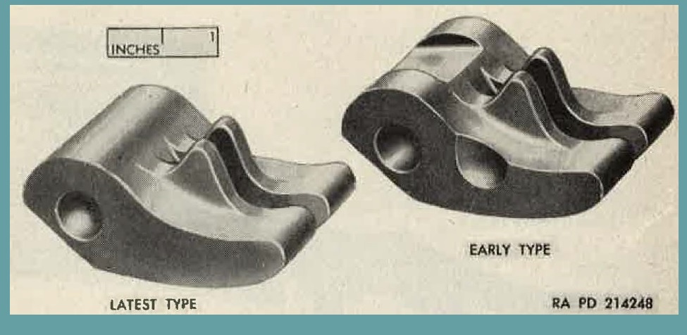
Fiugre 64. Comparison of accelerators.
65. Assembly
a. Assembly of Barrel buffer Body Group.
(1) If the barrel buffer body spring lock has been removed, force it into its undercut groove in the side of the barrel buffer body, with staking notch out and leading, and stake body into notch.
(2) Aline hole in accelerator with holes in body and insert accelerator pin, taking care that both ends of pin are flush with the sides of body.
b. Assembly of Barrel Buffer Assembly.
Place buffer spring over piston rod and seat it on the tube cap. Then place the flat surface of the spring guide on top of the spring with guide key in line with pin on notched side of piston rod. Following the procedure outlined in paragraph 63c ( 1), compress the buffer spring until the pin of the piston rod passes through the slots in the guide. Give the piston rod a one-qnarter turn to allow the pin to seat in its notches in the guide. Be sure the guide key is to the right of the notch in the piston rod with the notch up, when viewed from the rear.
c. Assembly of Barrel Buffer Group.
Insert barrel buffer assembly into barrel buffer body group from the rear. Engage the guiqe key in the key slot and push all the way forward. The air port in the buffer tube should be down, but it will function in any position.
66. Installation.
a. If barrel and barrel extension group were removed, insert barrel and barrel extension into the receiver until the lower projection on barrel extension contacts the bottom plate. Make sure that barrel buffer assembly is flush or projects slightly outside the encl of banel buffer body with the notch in the piston rod up (fig. 58). Hold barrel RA PD 214272
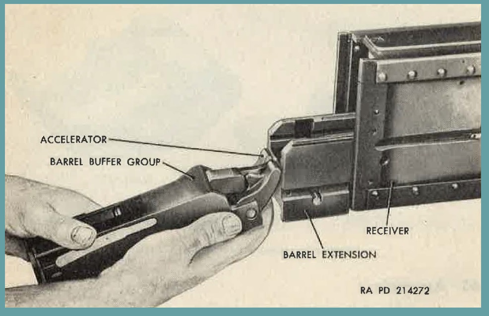
Figure 65. Installing barrel buffer group.
buffer group (fig. G5) in the right hand with the index finger holding up the accelerator. Engage notch in p-iston rod with barrel extension shank. Engage tips of accelerator with shoulders of barrel extension shank, and push barrel buffer group forward. This rotates the accelerator upward to lock barrel extension to barrel buffer group. Press down on tips of accelerator to insure complete locking.
b. with the groups locked together, raise them until clear of the bottom plate. Engage the barrel extension depressor grooves on the side plate breech lock depressors. Push the groups forward until locked in position, by buffer body spring lock snapping into its recess in receiver. Be sure barrel buffer guides enter grooves in receiver. Do not force assembly.
c. Install bolt groups (par. 60) and backplate assembly (par. 54).
67. General.
The barrel nnd banel extension group rtre recoiling components of the weapon. The front end of the barrel is supporlied by the recoil booster and the rear end by the barrel extension. The bead space of th weapon is adjusted by turning the barrel in or out of the barrel extension. and this adjustment is retained by barrel locking spring. See paragraphs 42 through 48 for an explanation of the functioning of the barrel and barrel extension group.
68. Removal.
a. Remove backplate assembly (par. 52).
b. Removeboltgroup (par.56).
c. Remove barrel buffer group (par. G2).
d. Remove barrel and barrel extension group by pulling it out through rear of receiver.
69. Disassembly.
a. Remove barrel by unscrewing it from the barrel extension (fig. 66).
Note. It is best to raise the barrel locking spring slightly to minimize wear of notches and spring when turning barrel. Do not strain the spring.
b. Push out breech lock pin assembly and remove breech lock (fig. 67).
c. Barrel locking spring is staked in position and should not be removed except to replace. To remove spring, lift staking and driveout spring, using a driftpin inserted in the hole at the rear of spring.
70. Maintenance.
a. Barrel 7265156 (standard) is the authorized barrel to be used in the gun. Thls barrel has a special liner and Chromium p1ated bore. The bearing at the muzzle end is machined on the barrel itse1f.
b. Bore and chamber must be kept clean of all metal ships and other fouling.
c. Replace barrel extension assembly if extension shank is misshapen, loose or broken.
d. Replace barrel locking spring if it is worn or broken. The locking projection should be sharp enough and spring action strong enough to securely hold the barrel in position. Spring should be lightgly staked in the extension.
e. Any burs on the bolt slideways or the breech lock slot in the extension should be removed, using a fine-grained sharpened stone or crocus cloth. The breech lock should slide smoothly in its ways.
f. Replace breech lock pin assembly if excessively worn by action of the depressors or if spring is missing or damaged.
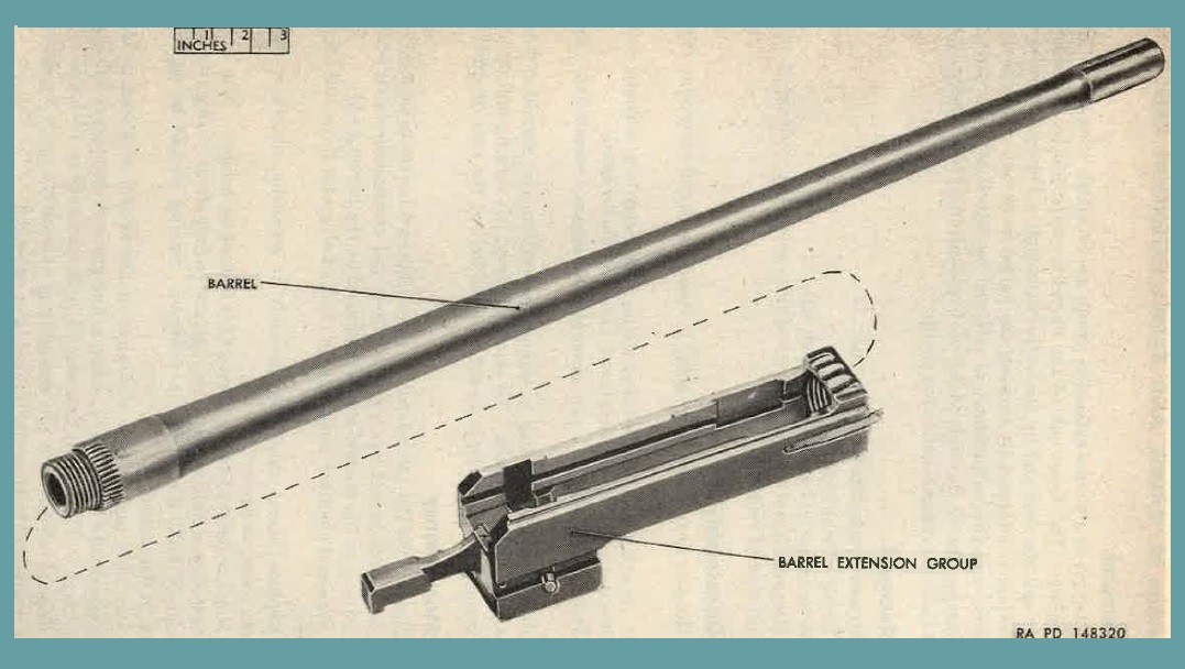
Figure 66. Barrel and barrel extension group.
g. When installing a new barrel, turn it all the way into barrel extension. Observe whether the threaded portion extends slightly past front end of extension. If it does not, barrel should be replaced because head space cannot be properly adjusted.
h. Inspection of barrel is described in (1) through (4) below.
(1) General. Due to the construction of the lined-plated barrel, conventional breech bore gages do not give an accurate indication of barrel condition. It has been found that wear on the lands toward the muzzle end occurs much faster than in the liner. The cal. .50 barrel erosion gage M6El-7319970 (fig. 21) was developed for inspecting lined-plated barrels.
(2) Visual inspection. Using a cal. .50 barrel reflector 5564255 (fig. 15), hold the barrel, so that its interior is illmninated, and examine the bore. Inspect the barrel as indicated in (a) and (b) below.
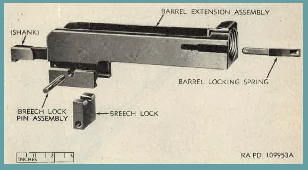
Figure 67. Barrel extension group - exploded view.
(a) Barrel is not bent or otherwise deformed.
(b) Bore is free of burs and large pits.
Fine pits are allowed in the chamber if they are not sufficiently large to cause extraction difficulties. Barrels will be replaced if lands are worn to the extent that accuracy is affected or if pits are one-half inch long and as wide as the lands.
(3) Instruction for use of cal. .50 barrel erosion gage 1116E1-7319970.
(a) Insert the gage tube into the breech end of the barrel 7265156 (fig. 68) to the point of contact of the gage stop shoulder and the barrel face and then push the gage rod forward until it is stopped by the gage head. The condition of the barrel can then be judged by reading the gage rod at the face of the gage tube. Three conditions of wear arc indicated by annular scribes on the gage rod as follows:
the scribe farthest from the gage rod handle indicates a new barrel, the next scribe shows a half-worn condition, and the scribe nearest the handle indicates an unserviceable condition. The gage stop is adjustable for positioning in either of two annular detents on the gage tube. Every time a barrel is gaged, the operation described above should be performed with the gage stop in both positions. If the gage indicates an unserviceable barrel at either setting of the stop, the barrel should be rejected.
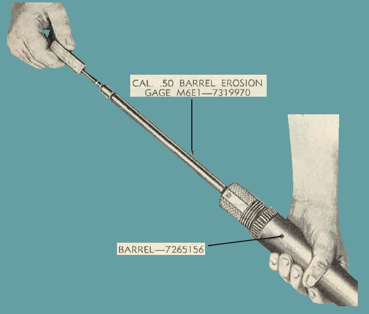
Figure 68. Inspecting the barrel, using cal. .50 barrel erosion gage M6E1 7319970.
(b) Because of dimensional tolerances in new barrels, the gage will sometimes indicate wear in unfired barrels and HALF-WORN position will be somewhat in error. This is not considered important because the middle-position reading is used for information only and barrels are rejected only when the gage reading reaches or closely approaches the third position.
(c) Barrels receiving normal use in combat or training will be rejected when the gage stop engages the rear detent; how- ever, since the service record of each barrel is seldom available under field conditions, readings must be taken with the stop in both positions. when firing has been conducted in extremely long, continuous bursts, the barrel becomes unserviceable because of wear in the liner rather than in the steel section of the liner.
Less severe firing schedules normally result in greater wear in the steel section ahead of the liner. Since the gage points are positioned in the liner when the gage stop is forward and in the steel section when the stop is rearward, a check is thereby afforded against any type of firing schedule to which the barrel may have been subjected.
(d) The only precaution to be observod in using the gage is to avoid expanding the gage points with the gagr rod prior to inserting the gage to its full depth in the barrel. Any instrument oil, applied to the gage to form a light coating, will suffice to protect it from corrosion. When the assembly is not in use, it should be kept in a form-fitting, rigid tray for protection.
(4) To check accuracy of gage.
The points (gage ring) should be checked with a micrometer while the gage rod is expanding the points in a normal manner. Check gage as described in (a) and (b) below.
(a) With the gage rod inserted to the NEW BARREL position, the average reading (average of the reading taken 90° apart) should be between 0.4980 and 0.5000 inch.
(b) With the gage rod inserted to the REJECTION position, the reading should be between 0.5065 and 0.5085 inch. Note. Barrels for the gun AN-M3 contain a llner that has a substantial quantity of valuable material that can be used in manufacturing new liners. The return of unserviceable barrels is therefore desirable in order that these liners may be salvaged. Return barrels to field maintenance personnel for disposition.
71. Assembly
a. If barrel locking spring has been removed, insert it in its recess as far as it will go; restake in same position.
b. Slide breech lock into its slot in barrel extension, with the beveled face to the front and the notch on top. Insert breech lockpin assembly, making sure that both ends are flush with the sides of barrel extension. Be sure that pin is retained by spring when assembled.
c. Screw barrel into barrel extension as far as it will go, and then back out 8 or 10 notches to facilitate assembly of the group into the gun.
Note 1. It is best to raise the barrel locking spring slightly to minimize wear of barrel notches and spring when turning the barrel. Do not strain the spring.
Note 2. With barrel screwed all the way into the extension, the recoiling parts will not go fully into battery position, and difficulty may be encountered when installing barrel and barrel extension group and barrel buffer group.
72. Installation.
a. Insert barrel and banel extension group (fig. 3) into the rear end of receiver until the lower projection on the barrel extension contacts the bottom plate. Install barrel buffer group aa outlined in paragraph 66. Raise the groups to clear the bottom plate and push forward in the receiver until locked in position by buffer body spring lock.
b. Install bolt group (par. 60).
c. Install backplate assembly (par. 54).
Note. No attempt should be made to opera1e the gun until head space and timing have been adjusted and checked (Pars. 14 and 15). For installation of new barrel, see paragraph 70g.
73. General.
a. The cover group is located on the top-front of the receiver and is basically composed of the cover, belt feed slide group, cover extractor cam, cover extractor spring, and Lelt feec1 lever.
b. The function of the cover group is to pull the ammunition belt into the gun and enable the extractor to pull a round from the belt.
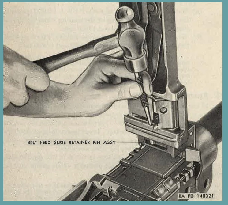
Figure 69. Removing belt feed slide retainer pin assembly.
For a detailed description of the functioning of the cover group, see paragraphs 42 through 48.
74. Disassembly.
a. With cover raised, insert a driftpin into the half-round hole appearing in the belt feed slide retaniner and tap out the belt feed slide retainer pin assembly (fig. 69).
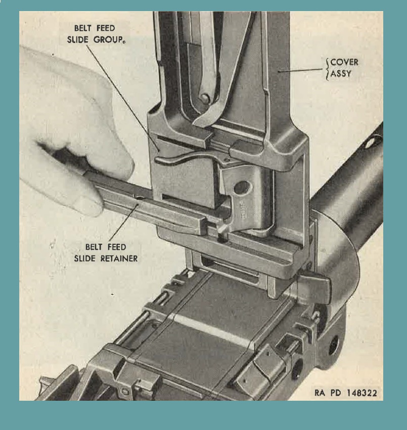
Figure 70. Removing belt feed slide retainer.
b. Withdraw belt feed slide retainer from cover nssembly (fig. 70), and lift belt feed slide group (fig. 71) out of its sent.
c. Aline front end of belt feed lever with the slot. in cover and lift lever off the stud. Take care not to lose belt feed lever plunger and spring.
d. Remove belt feed lever plunger and spring from the hole in the lever.
e. Using a driftpin, depress the belt feed pawl arm locating plunger (figure 72) (in center of arm), and slide arm away from belt feed pawl pin. Hold pawl down against spring pressure, push out belt feed pawl pin (figure 73) and remove pawl and springs from slide.
f. Lift end of cover latch spring from groove in the cover assembly (figure 74) and turn slightly, so that it rests on the cover extractor spring. Compress the latch spring by firm pressure of the thumb, slide the spring away from the latch, and remove.
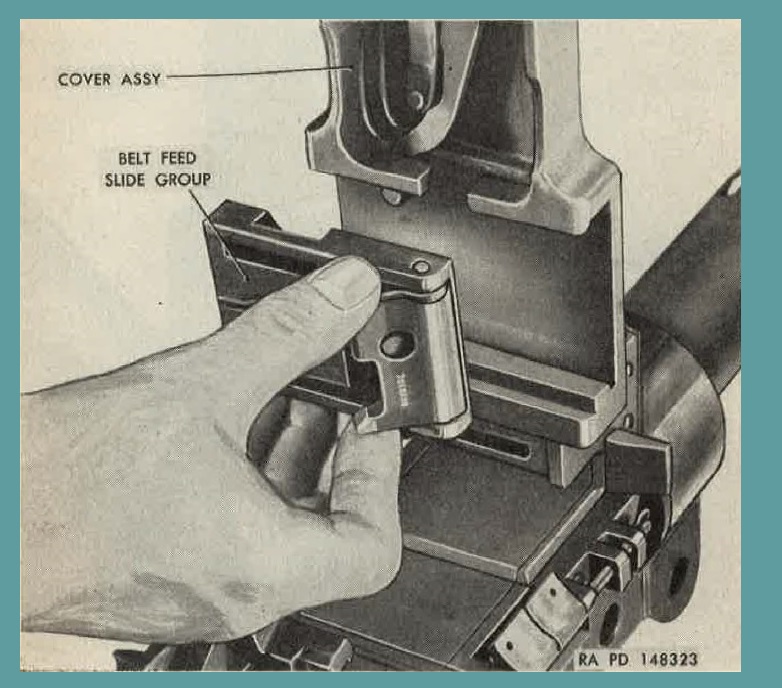
Figure 71. Removing belt feed slide group.
g. To remove cover extractor spring (figure 75), depress end of spring that is retained by the recess in the extractor cam and move laterally out of recess. Two types of cover assemblies may be in service. Cover assembly 7161710 is the basic type and has an extractor cam riveted to the cover. This extractor cam has a recess to retain the cover extractor spring. Alternative manufacture cover a8sembly 7266180 (figure 75) has an integral extractor cam, however, a separate extractor spring retainer is riveted in place in a hole in the left side. Disassembly of the extractor spring retainer is not authorized by organizational personnel.
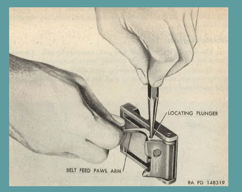
Figure 72. Depressing locating plunger to remove belt feed pawl arm.
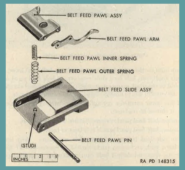
Figure 73. Belt feed slide group - exploded view.
h. To remove cover latch, remove shaft cotter pin and washer. Turn the latch shaft to the latched position, and withdraw the shaft from the cover.
75. Maintenance.
a. Check to see if correct belt feed pawl assembly is used. All pawl assemblies that are not marked "7265639" are to be replaced.
b. Examine cover extractor spring stud, extractor cam, extractor spring retainer and latch spring stud for looseness; if loose, notify field maintenance personnel.
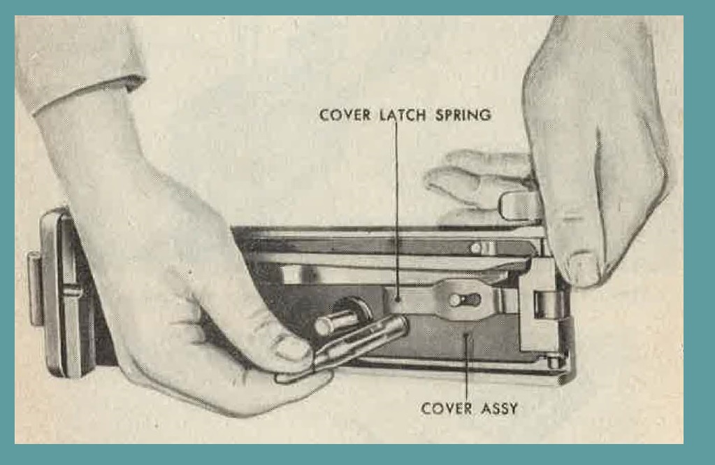
Figure 74. Removing cover latch spring.
c. Any burs on the cover latch extractor cam, belt feed lever, pivot stud, belt feed slide retainer, or belt feed pawl assembly should be removed, using crocus cloth or a fine grained sharpening stone. Be careful not to change shape or dimensions of parts.
d. If the cover extractor spring or cover latch spring is weak or broken, it should be rnpl cteed.
e. Replace belt feed pawl springs that are weak or broken.
f. Replace belt feed pawl arm if it is bent or broken.
g. The belt feed lever must have free movement. Any binding due to burs, rust, or broken parts should be corrected. If lever is bent or the diamond-shaped bolt cam protrusion is badly worn, it should be replaced.
h. Be sure cover latches securely.
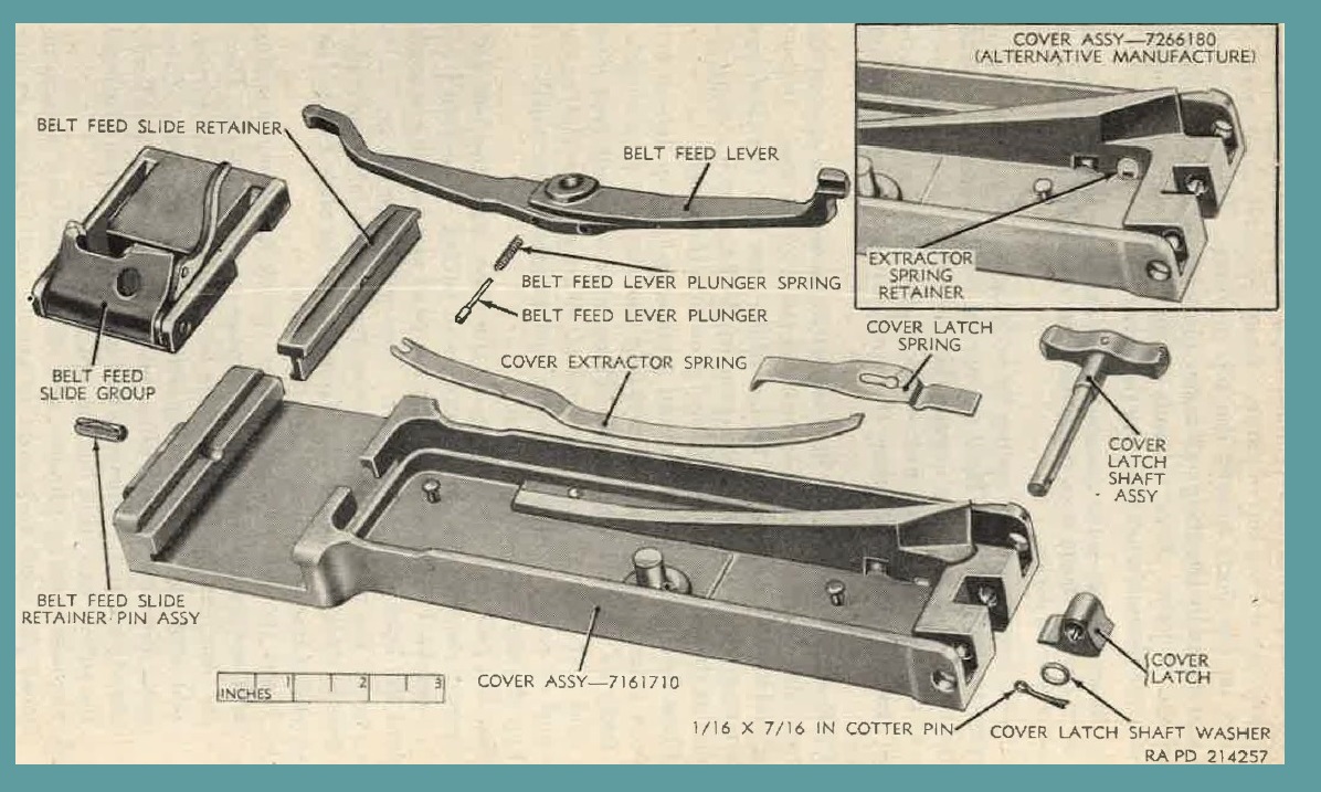
Figure 75. Cover group - exploded view.
76. Assembly.
a. To assemble latch to cover, place fatch between shaft bosses with the keyway toward the top of cover. Insert the latch shaft assembly with key on the shaft toward the top of cover. Place washer on shaft and secure by inserting new cotter pin with the head toward the hinged end of cover. Bend the ends of pin closely against the shaft to avoid interference when latching the cover.
Note. Shaft assembly can be assembled from either side; however, for clearance, the shaft lever should be on the opposite side from that of the charger or other bolt retracting device.
b. Install cover extractor spring by hooking the slotted end under the extractor spring stud. Hold the spring firmly against the stud, and for early designed type, engage the curved end in the retention recess of the extractor cam. For covers of present design, engage the curved end of the spring under the notch of the extractor spring retainer.
c. Place cover latch spring in cover with the bent end against the cover and the enlarged hole over the cover latch spring stud. Depress spring and slide it toward the latch. Make sure that the latch end of the spring rides over the projecting wing of the latch. Snap the bent end of the spring into the lateral groove in the cover.
d. Place belt feed lever spring and plunger in the top hole of belt feed lever (cover open) for left-hand feed (bottom hole for the righthand feed) as shown in figure 13. Place lever over belt feed lever pivot stud and position the front end of lever over the slot in the hinge encl of cover. Depress plunger and position lever until it is seated on the stud against the cover.
e. Seat the belt feed slide group in the cover with the belt feed pawl toward the side the ammunition is to be fed. The feed pawl must be assembled to the slide, so that the pawl arm locating plunger is toward the latch end of the cover. This will place the pawl arm to the rear of the pawl. Proper assembly for both left- and right hand feed is shown in figure 13. To assemble the slide group (fig. 73), proceed as instructed in (1) and (2) below.
(1) Insert the belt feed pawl inner spring in the outer spring and seat the springs over the springs stud in the slide. Place the pawl in the slide, so that the free ends of the springs seat squarely in the spring seat recess of the pawl. Press pawl clown on springs, aline the holes in slide and pawl, and insert pawl pin. Make sure that grooved end of pin is toward the side of pawl that has the locating plunger.
(2) Depress locating plunger, and slide forked end of arm on pawl pin until fork seats in groove and locating plunger snap through hole in arm. Pawl arms of present manufacture cannot be assembled incorrectly. Early-type belt feed pawl arms should be assembled so that convex curve of the arm is away from the slide or cover, when assembled, and the cmve of the free end pointing down.
f. Place assembled slide group (fig. 71) in its ways (grooves) in the cover assembly with the pawl end of slide toward the side from which the gun is to be feel. Engage the belt feed lever in its recesss in the slide. Slide belt feed slide retainer (fig. 70) into place on the cover, aline pinhole in retainer and cover, and insert belt feed slide retainer pin assembly from the bottom (cover raised). Operate slide group by mov1ng the belt feed lever to see that there is no binding. With cover closed, check to see that belt feed pawl is on the side from which the ammunition is fed.
77. General.
The receiver and barrel jacket group consists primarily of the receiver assembly, barrel jacket, and recoil booster. The purpose of this group is to house the working parts of the gun as woH ns to support the fixed parts that contribtrte to operation. Dctai1ed functioning of the components of the receiver and barrel group are explained in paragraphs 42 through 48.
78. Disassembly.
a. Remove the belt holding pawls, sleeves, and springs by withdrawing the beIt holding pawl pin assembly. Be careful not to loose pawl springs. If pawl pin spring does not cam down freely, depress bofore withdrawing pin; do not force.
b. Remove the link chute adapter assembly (figure 76) by lifting straight up from the belt holding pawl pin. withdraw pin as explained in step "a" above.
c. Trunnion block cover (figure 76) can be removed by driving out the two cover pins and lifting the cover off the trunnion block. These parts serve no functional purpose in the gun AN-M3.
d. To remove the extractor switch, release the switch pivot nut spring pin (or cotter pin in some guns) from the switch pivot nut. Unscrew nut, and pul1 ont the switch and switch spring. (The switch pivot nut spring pin replaces the cotter pin and is not as susceptible to breakage.)
e. To remove the breech lock cam, pull the cotter pin from the breach lock cam bolt. Which protrudes from the bottom plate of the receiver, and remove the nut. Withhdraw the brnech lock cam bolt and cam from the inside of the receiver.
Note. The breech lock cam should not be removed except for replacement or when cleaning is imperative.
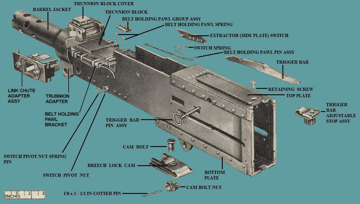
Figure 76. Receiver and barrel jacket group - partial exploded view.
f. To remove trigger bar, lift the lock and rotate the trigger bar pin assembly (figure 76) about 90°. The projection on the pin assembly will then aline with the key slot in the side plate and the pin assembly can be removed by pulling it from the gun. Removing the pin assembly will free the trigger bar. Remove trigger bar.
Note. There are two trigger bar pin assemblies that are usnllle. Pin assembly 7313106 is of later manufactme (Fig. 77).
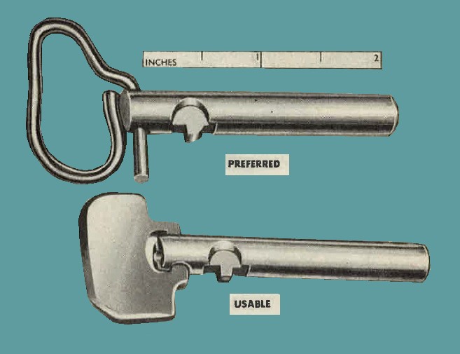
Figure 77. Comparison of trigger bar pin assemblies.
g. To remove the trigger bar adjustable stop assembly (figure 76), remove the trigger bar adjustable stop retaining screw from top plate and free assembly from trigger bar stop, which serves as a positioning pin. To disassemble stop assembly, unscrew adjusting nut and remove spring.
h. Remove recoil booster (figs. 78 and 79) by unscrewing the two screws locking the booster to barrel jacket, and unscrew the booster from the jacket, using the cal. .50 combination wrench 7161767 (fig. 78).
i. Release the trunnion block lock, located in the under side of the trunnion block, by pulling it to the rear and giving it a one-quarter turn. The projecting cotter pin will hold it out of engagement with the adapter. Assemble the body of the trunnion adapter tool 7265626 (fig. 18) to the front end of the receiver by inserting the pin through the body and receiver (A, fig. 80). Place the wrench on the unlocking screw assembly. Start rotating the trnnnion adapter counterclockwise by turning the locking screw assembly. After the trunnion adapter has been snapped out 0£ its assembled position, remove the body of the trunnion adapter tool from the receiver. Assemble the adapter tool wrencl1 and extension together, and attach the wrench end to the tnnmiou adapter by the adapter tool pin (B, fig. 80). The trunnion may now be completely removed together with the shim.
Note. Be sure truunion block lock is retracted completely ancl is held by the cotter pin.
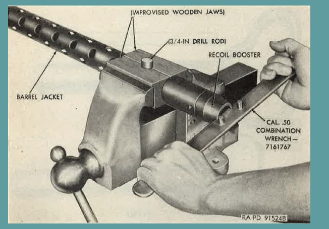
Figure 78. Removing recoil booster, using cal. .50 combination wrench 7161767.
j. If the recoil adapter assembly is to be removed, notify field maintenance personnel.
79. Maintenance.
a. Carbon deposits may form in the recoil booster and decrease the rate of fire of the gun. Remove carbon from inside the booster by scraping. Check booster screws for tightness and staking.
b. Remove all dirt, burs, or foreign matter from under the breech lock cam.
c. Replace weak or broken belt holding pawl springs.
d. Replace barrel jacket if it is bent or binds against the barrel.
e. Replace extractor switch spring if broken or weak.
f. Replace belt holding pawl pins if they do not fit snugly or are broken or if positive retention is doubtful.
g. Be sure extractor cam and breech lock depressors are tightly riveted to the side plates and are not burred or unduly worn.
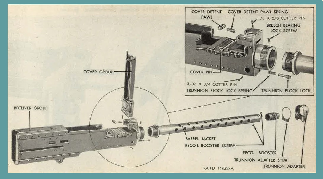
Figure 79. Receiver and barrel jacket group - exploded view.
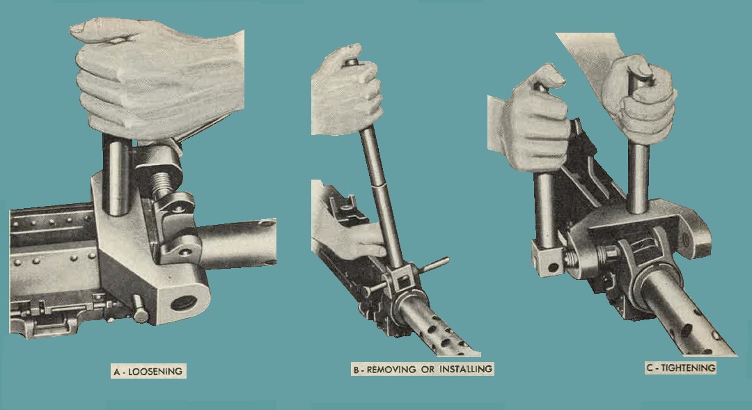
Figure 80. Removing and installing trunnion adapter, using trunnion adapter tool 7265626.
h. A clearance or at least 0.005 inch must be maintained between the top plate bracket and the bolt. If the required clearance does not exist, attempt to correct it by changing the bolt group. If the aforementioned methods do not provide the correct clearance, return gun to field maintenance personnel.
i. If any rivets on receiver are loose, notify field maintenance personnel.
j. Check link chute adapter assembly for loose elastic stop nuts.
Elastic stop nuts with fiber inserts are to be replaced by nuts with nylon inserts if available. The fiber inserts deteriorate when continually subjected to saturation with cleaning solvents and oils.
k. Check link chute adapter assembly for beveled edge. Replace early type with modified type.
80. Assembly.
a. Screw the recoil booster into the barrel jacket, using cal. .50 combination wreneh 7161767 (fig. 7), unti1 the holes in the jacket and booster are in ailinement. Insert, tighten, and stake the two screws.
b. Position the trigger bar adjustable stop assembly (fig. 76) on the rear trigger bar stop (pin).. Thread the retaining screw through the top pJlate cover, top plate, and stop body and stake screw. Seat adjusting nut spring on the top with prongs forward and dowu and thread nut on the stop with notches up. For adjustment of trigger bar adjustable stop assembly, see paragraph 15. When assembled, be sure end of screw does not intetefere with 1evel seatiug of the spring in the body.
c. Raise the lock of the trigger bar pin assembly in line with the pin, and insert the pin through the left side plate and holddown bracket.
Note. Take care to match the key in the pin with the key slot in the side plate. Position the trigger bar in the top plate bracket, with the long encl forward and the bowed surface upward. When positioning, the trigger bar should project approximately five-sixteenths of an inch beyond the rear trigger bar stop. With the trigger bar held in position, insert the trigger bar pin through it. After insertion, rotate the pin 90° nntil . topped by the flange of the top plate, and push the lock down flat against the side plate.
d. To replace the breech lock cam, place it in the receiver, with the cam surface up and sloping to the rear. Place the lower projection of the cam through the hole in the bottom plate and insert the breech lock cam bolt from the top. Screw the castellated nut on the bolt, with the notches (castellations) against the surface of the bottom plate, and draw it tight. Aline the nearest castellation in the nut with the cotter pin hole in the bolt and insert a new cotter pin. Spread prongs of pin and bend snugly around nut. Be sure head 0£ cam bolt does not project above cam.
Note. When the breech lock cam is properly assembled, it should float slighlly, to avoid any binding of the barrel extension in its guides in the cam. The clearance between the cam and the bottom plate should be between 0.001 and 0.008 inch and should be measured with a feeler gage at the point indicated by the arrow in figure 81. If proper clearance cannot be provided with the nut drawn tight and the cotter pin inserted, try other nuts, bolts, or cams until this clearance is obtained.
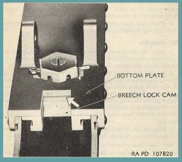
Figure 81. Measuring point for breech lock cam clearance.
e. To install the extractor ( side plate) switch (fig. 82) , first insert the straight end of the switch spring in the switch recess of the left side plate, with bent end of spring outside the recess. Then start the switch pivot into its hole in the side plate. Make sure the lug on the switch rides on top of the spring. Rotate the switch downward and press against side plate until spring and switch snap into the recess. Thread the nut on the projecting pivot and draw up snugly, hut do not force. Loosen nnt slightly if necessary to line up the notches (castellations) in the nut with the hole in the pivot. Insert the switch pivot nut spring pin {or cotter pin on some guns). Try the switch to see that it pivots freely, snaps bade into position, and there is no unnecessary sideplay.
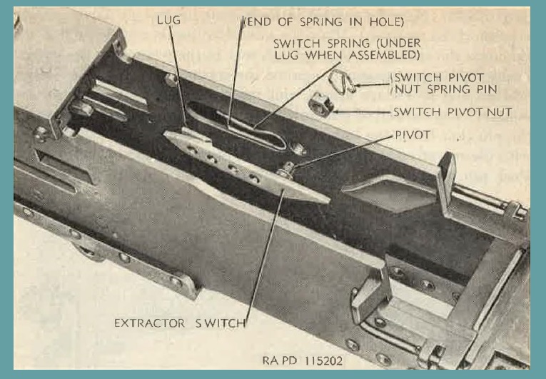
Figure 82.
f. The belt ho1ding pawl group assembly (fig. 3) is placed in, position on the side of the receiver the gun is to be fed from. To assemble on the gun, place the right and left-hand pawls on the belt holding
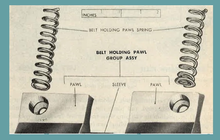
Figure 83.
pawl sleeve. Seat the springs in their seats in the belt holding pawl bracket of the receiver. Place the assembled pawls and sleeve in position over the springs so that springs seat in the recesses in the pawls. Depress the group assembly against the springs until the holes in the bracket and pawls are alined, and insert belt holding pawl pin assembly. Curved end of pin may be either to front or rear. However, the pin that holds the link chute adapter assembly must be installed with the curved end to the rear, to obtain proper seating of the adapter. Push pin until securely locked and turn curved end down.
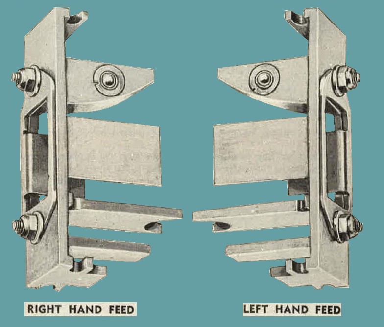
Figure 84. Comparison of link chute adapter assemblies assembled for left and right hand feed.
g. Insert the remaining belt holding pawl pin assembly securely in the opposite bracket and place the link chute adapter assembly (fig. 84) in position on the pin, with the curved front stop forward. Figure 85 shows the belt holding pawls and link chute adapter assembly installed £or right-hand feed. The link chute adapter assembly is always installed on the opposite side of the feedway from the belt holding pawls. When in position, the curved front stop should be forward and the long end of the cartridge guide up. Position of the guide can be changed by removing the nuts and withdrawing and reversing the guide. When assembling, be sure the nuts are tight. In adapters of recent design, there is only one positioning ball in the front stop of the adapter. This ball should be on top when adapter is installed. To change position of ball, push out the positioner assembly, containing the ball from the side opposite the ball, and then reseat it in the opposite side of the stop.
h. To install the trunnion adapter, disengage the trunnion block Jock (par. 78i), place shim in position, and screw on adapter. ·with the wrench ( and extension) o:f the trunnion adapter tool 7265626 ( B, fig. 80) attached to the trunnion adapter, turn the adapter to nearly
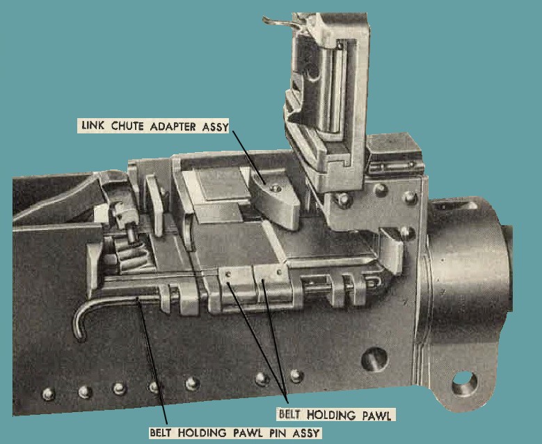
Figure 85. Feedway section of receiver - Parts assembles for right hand feed.
its assembled position. Remove the wrench (and extension), and attach the trunnion adapter tool body to the bottom front end of the receiver (C, fig. 80). with the adapter tool wrench, turn the locking screw assembly until the hole in the trunnion adapter alines with the trunnion block lock located in the under side of the trunnion block. If, when the adapter is snugly screwed on, the hole in the adapter does not aline with the lock, use a thicker shim (par. 4).
Note. Shims are numbered according to their thickness. 'l'he larger the number, the thicker the shim.
With shim and adapter alined, turn trunnion block lock one-quarter turn and allow it to seat in hole in adapter. Be sure lock passes through shim and fully seats in adapter and that cotter pin in lock is not bent or broken.
81. General
Field maintenance of the materiel, for the most part, entails replacement of the unserviceable parts or assemblies. It usually means turnaround maintenance, i. e., repair and return to using organization. In the event the materiel is found unserviceable or incipient failures are disclosed, it will be thoroughly and completely inspected, put into the best possible condition that time, material, and tactical circumstances allow, and returned to the using organization ready for immediate use.
82. Procedures
a. Burs on components set up by firing should be removed by stoning. Burs on working surfaces such as cam grooves in bolt, engaging surfaces of sear slide, and roughness on working parts such as accelerator, breech lock, and breech lock cam should be removed with a fine-grained stone.
Caution: Exercise care to stone evenly and lightly and not to remove more metal than is absolutely necessary. Parts or assemblies should not be altered in any way that would make such parts noninterchangeable or affect their proper operation or function.
b. Rust may generally be removed with a cloth moistened with light oil or rifle-bore cleaner. If this does not suffice, use crocus cloth.
c. Clean and oil parts and assemble groups before replacing them on gun.
d. Guns that have been fired 15,000 rounds will be withdrawn from service and tagged for ordnance depot rebuild. Inspectors classifying guns for ordnance depot rebuild will record all deficiencies on AF Form 185 at time of inspection.
83. General.
Tools, equipment, and maintenance parts over and above those available to the using organization are supplied to field maintenance units for maintaining and repairing the materiel.
84. Parts.
Field maintenance parts are listed in the appropriate column of the Department of the Army Supply Manual ORD 8 SNL A-67, which is the authority for requisitioning replacements.
85. Common Tools and Equipment.
Standard and commonly used tools and equ1pment having general application to this materiel are authorized for issue by TA and TOE. They are not specifically identified in this manual.
86. Special Tools and Equipment.
The special tools and equipment 111 table IV are listed in Department of the Army Supply Manual ORD 6 SNL J-12. This tabulation contains only those special tools and equipment necessary to perform the operations described in this manual, is included for information only, and is not to be used as a basis for requisitions.
TABLE IV. Special Tools and Equipment for Field Maintenance.
| REFERENCES | |||||
| Number | ITEM | IDENTIFYING No. | FIGURE | PARAGRAPH | USE |
| 1 | BRUSH, cleaning, cal. .50, M4 | 5504037 | 15 | 39b (1) | To clean bore. |
| 2 | BRUSH, cleaning, chamber, M6 (bristle) | 6108828 | 15 | 7b (5) (d) | To clean the chamber of the gun. |
| 3 | BRUSH, cleaning, firing pinhole, cal. .50. | 7162702 | 15 | 10c, 58d | Used with cal. .45 cleaning rod M4 - 5564102 to clean firing pinhole in bolt. |
| 4 | COUPLER, disconnector, cal. .50, M20 | 7146365 | 20,23 | 17,31 | To remove, insert, or aline cartridges. |
| 5 | END, cleaning patch | 7162704 | 15 | 10c | Used with cal. .45 cleaning rod M4 - 5564102 to clean firing pinhole in bolt. |
| 6 | EXTRACTOR, ruptured cartridge case, cal. .50. | 7160041 | 86 | 87 | To remove ruptured cartridge cases. |
| 7 | GAGE, barrel erosion, cal. .50, M6E1 | 7319970 | 21, 68 | 70h (1) | To detect excessive barrel erosion. |
| 8 | GAGE, headspace and timing, cal. .50. | 5351217 | 7, 8, 17 | 14, 15 | To check head space and timing of gun. |
| 9 | HANDLE, bolt. | 6008583 | 20 | 36f, 87a | To hand-operate gun. |
| 10 | MACHINE, link-delinking, hand, cal. .50, M17. | 7160003 | 22 | 17, 32 | To link or delink cartridges. |
| 11 | REFLECTOR, barrel, cal. .50. | 5564255 | 15 | 70h (2) | To inspect bore of gun. |
| 12 | ROD, cleaning, cal. .45, M4 | 5564102 | 16 | 10c, 58d | Used with cal. .50 firing pinhole cleaning brush 7162702 or cleaning patch end 7162704 to clean the firing pinhole in bolt. |
| 13 | ROD, cleaning, cal. .50, MG. | 6535442 | 16 | ----- | Used with bore-cleaning cloth to clean gun tube. |
| 14 | ROD, cleaning, jointed, cal. .50, M7. | 6535441 | 16 | 7b (5) (e), 39b (1) | Used with cal. .50 cleaning brush M4 - 5504037 to clean the bore. |
| 15 | ROLL, tool, canvas, 24 pockets, 26 1/4 x 14 1/2. | 7161569 | ----- | ----- | ----- |
| 16 | TOOL, assembling and disassembling, oil buffer, cal. .50. | 7319903 | 86, 88 | 98, 101f | To disassemble and assemble barrel buffer spring. |
| 17 | TOOL, depressor, adj screw plunger, cal. .50. | 7265950 | 19, 40 | 52c | To depress adjusting screw plunger when removing or installing backplate adjusting screw. |
| 18 | TOOL, release, buffer spring lock, lgh 10 in, cal. .50. | 7161816 | 17 | 62b | Used to remove teh body and buffer assembly from receiver. |
| 19 | TOOL, removing, firing pin spring, cal. .50. | 6243646 | 71, 51 | 57k, 59b | To remove and install firing pin spring. |
| 20 | TOOL, trunnion adapter | 7265626 | 18, 80 | 78i, 80h | To remove and install trunnion adapter. |
| 21 | WRENCH, adapter, cal. .50. | 7162907 | ----- | ----- | ----- |
| 22 | WRENCH, comb, cal. .50. | 7161767 | 19, 40, 78 | 52c, 54d, 78h, 80a | To remove and install recoil booster and backplate adjusting screw. |
| |
87. Cal. .50 Ruptured Cartridge Case Extractor 7160041
This extractor (figure 86) is for the purpose of extracting ruptured cartridge cases (head torn off) from the chamber of the barrel of guns equipped with chargers or like retracting devices. Use of extractor is explained in "a" through "c" below.
a. Disconnect the firing circuit, raise the cover, and fully unload the gun. Retract the bolt by means of bolt handle 6008583 (figure 20), or other retracting device, and place the ruptured cartridge case extractor in the T-slot of the bolt in the same manner as a cartridge, so that it is held in line with the bore by the ejector of the extractor assembly of the gun. With the cover raised, it may be necessary to press the extractor assembly down by hand to aline the ruptmed cartridge case extractor with the bore.
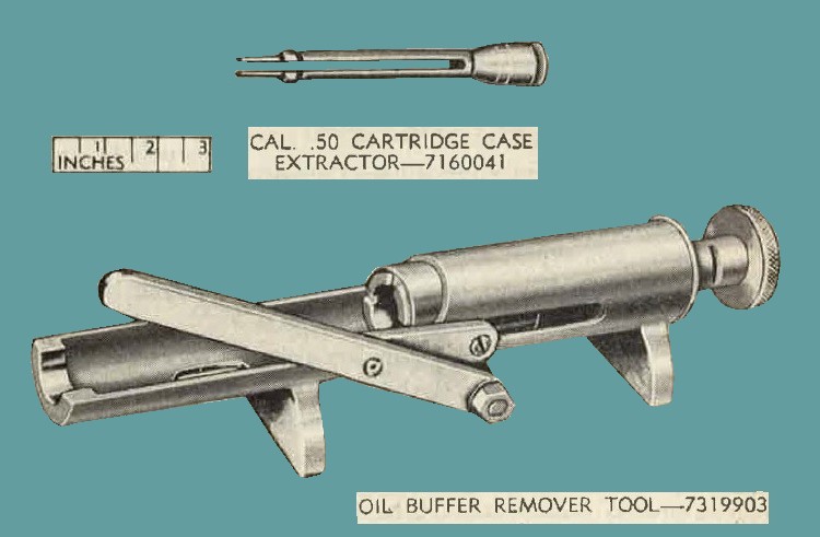
Figure 86. Special tools for field maintenance.
b. When sure that the ruptured cartridge case extractor is in line with the bore and held firmly in the T-slot of the bolt, allow the bolt to spring forward into battery under action of the driving springs. This will force the ruptured cartridge case extractor through the ruptured cartridge case and the shoulders on the extractor will spring out in front of the case.
c. Fully retract the bolt. The ruptured case will be drawn from the chamber.
Note. If the gun is properly head spaced, the ruptured cartridge extractor may be placed in the feeclway, engaged with the extractor of the gun, and the cover closed. The extractor can then be fed into the T-slot like an ordinary cartridge.
88. General.
a. Scope.
This section provides specific instructions for the technical inspection by field maintenance personnel of guns in the hands of the user or when received for repair in maintenance shops. It also briefly describes the in-process inspection of guns during repair and final inspection after repair has been completed. Trouble shooting information is incorporated whenever applicable as a normal phase of inspection.
b. Purpose of Inspections.
Inspections are made for the purpose of-
(1) Determining the condition of an item as to serviceability.
(2) Recognizing conditions that would cause failure.
(3) Assuring proper application of maintenance policies at prescribed levels.
(4) Determining the ability of a m1it to accomplish its maintenance and supply missions.
c. Types of Inspections.
In general, four categories of inspection are performed by field maintenance personnel.
(1) Technical inspection.
This is a periodic overall inspection performed on guns in the hands of the using organization and an inspection performed by field maintenance personnel when guns are returned for repair.
(2) In-process inspection.
These are inspections performed in the process of repairing (field maintenance) guns as described further in this chapter: This is to insure that all parts conform to the prescribed standards, that the workmanship is in accordance with approved methods and procedures, and that deficiencies not disclosed by overall inspections are found and corrected.
(3) Final inspection.
This is an acceptance inspection performed by a final inspector after repair has been completed, to insure that the gun is acceptable for return to using organization.
(4) Spot check inspection. This is a periodic overall inspection· performed on only a percentage of the guns in each unit, to determine the adequacy and effectiveness of organizational maintenance.
89. Technical Inspection.
a. General.
Warning: Before starting a technical inspection, be sure to clear the weapon. Do not touch the firing mechanism until the gun or guns have been cleared. Inspect the chamber to insure that it is empty and check to see that no ammunition is in a position to be introduced. Avoid live ammunition in the vicinity of the work.
(1) Preparatory procedures.
(a) Check to see that the gun has been cleaned of all corrosionpreventive compound, grease, excessive oil, dirt, or foreign matter that might interfere with proper functioning or obscure the true condition of parts.
(b) Make an overall inspection of the gun for general appearance, condition, operation, and manual functioning. Use dummy cartridges.
(2) Inspection guide. Table V lists the prescribed standards that are used as a guide for the inspection of the guns.
TABLE V. Inspection Guide for Cal. .50 Basic Aircraft Machinegun AN-M3
| Num | Points to be Inspected | Overall Inspection | Final Inspection Field Maintenance |
| 1 | FINISH | Intact, clean, and free of rust. | Dull Black or grey finish. |
| 2 | BORE | Light pitting and lands sharp. | Minimum pitting and sharp lands and groove. |
| 3 | HEAD SPACE | 0.202 to 0.206 in. | 0.202 to 0.206 in. |
| 4 | TRIGGER BAR CLEARANCE | 0.005 in. | 0.005 in. |
| 5 | BELT PULL | 35 lb. | 35 lb. |
| 6 | BUFFER PLATE | 1/4 - in. projection | 1/4 - in. projection |
| 7 | COVER LATCH CLEARANCE | 0.010 in. max | 0.010 in. max |
| 8 | CLEARANCE BETWEEN SIDE PLATE AND BOLT | 0.012 to 0.024 in. | 0.012 to 0.024 in. |
| 9 | BREECH LOCK CAM | 0.001 to 0.008 in. | 0.001 to 0.008 in. |
| 10 | SEAR RELEASE | ----- | 24 lb. max. |
| |
b. lnspection of Materiel in Hands of Using Organization.
(1) General. See TM 9-1100/TO 39-1-7 for responsibilities and fundamental duties of inspecting personm1l, the necessary notice and preparations to be made, forms to be used, and general procedures and methods to be followed by inspectors. Materiel to be inspected includes organizational spare parts.
and equipment and the stocks of cleaning and preserving materials. In the course of this inspection, the inspector will perform the checks-described in (a) through (h) below.
(a) Determine serviceability, i. e., the degree of serviceability, completeness and readiness for immediate use, with special reference to safe and proper functioning of the materiel. If the materiel is found serviceable, it will be continued in service. In the event it is found unserviceable or incipient failures are disclosed, the deficiencies will be corrected on the spot or advice given as to corrective measures when applicable or, if necessary, the materiel will be tagged for delivery to and repaired by field maintenance personnel.
(b) Check causes of mechanical and functional difficulties that using organizations may be experiencing and check for apparent results of lack of knowledge, misinformation, neglect, improper handling and storage, security, or preservation.
(c) Check on application of all authorized technical orders to see that no unauthorized alterations have been made or that work beyond the authorized scope of the unit is being attempted. The following technical orders are considered mandatory at time of preparation of this manual; however, also check TO 00-1-39 and the current technical order files for any additional technical orders promulgated subsequently.
| TO 00-35D-185 | AF Form 185 - Maintenance and performance report. |
| TO 39A-5A-2 | Inspection and rework of barrel 7162259. |
(d) Instruct the using personnel in proper preventive maintenance procedures where found inadequate.
(e) Check on completeness of the organizational maintenance allowances and procedures for obtaining replenishments.
(f) Check conditions of storage of general supplies and ammunition.
(g) The inspector should report to the responsible officer any carelessness, negligence, unauthorized modifications, or tamperings. This report should be accompanied by recommendations for correcting the unsatisfactory conditions.
(h) Initiate a thorough report on materiel awaiting repair, with reasons therefor, for further appropriate action.
(2) 0perational inspection.
(a) Check proper adjustment of backplate screw.
(b) Check barrel for wear.
(c) Check position of components for left- and right-hand feed.
(d) Check head space and timing,
(e) Cheok gun for smooth operation.
c. Inspection of materiel Received in Feld Maintenance Shops.
(1) Information 1n "b" above applies also to the inspection of materiel received in field maintenance shops.
(2) Inspect materiel for repairs to be ta.gged for depot maintenance.
(3) Table VI lists malfunctions, probable causes, and corrective action that pertains to field maintenance.
TABLE VI. Troubleshooting - Field Maintenance.
| MALFUNCTION | PROBABLE CAUSE | CORRECTIVE ACTION |
| Warped cover | Gun firing out of battery due to firing pin retaining pin not being installed during assembly of firing pin and extension assembly. | Correct assembly of firing pin and extension assembly (par. 59). Replace cover group (par. 109). |
| |
||
| Ruptured cartridge case. | Gun firing out of battery due to firing pin retianing pin not being installed during assembly of firing pin and extension assembly. | Correct assembly of firing pin and extension assembly (par. 59). Remove rupture cartridge case (par. 87). |
| |
||
| Damaged barrel buffer body assembly. | Interference of the barrel buffer body and breech lock depressors. | Replace barrel buffer body assembly (par. 65). |
| |
||
| Failure to feed - Gun stops firing with recoiling parts out of battery position. | Broken backplate buffer washer springs. | Replace buffer washer spring group assembly (par. 54). |
| |
90. Removal and Disassembly.
See paragraph 52 for removal and dissembly of backplate assembly.
91. Inspection.
a. Check backplate assembly for fit in grooves of receiver. It must fit tightly but must not bind so that it cannot be removed by hand.
b. Inspect all components for excessive wear, rust, and burs.
c. Check buffer washer springs for cracks (early manufacturer). Springs should ring clearly when dropped on stone or metal surface. Inspect backplate spring (coil-type) and buffer plate disk for cracks and weakness.
d. Check backplate adjusting screw for burred threads; replace if necessary.
e. Check adjusting screw plunger; replace if damaged.
f. Check latch lock and latch for functioning in backplate. If latch swings by stop surface, replace latch.
92. Repair.
a. Replace all broken, badly worn, or otherwise unserviceable parts.
b. Remove all rust and burs from components (par. 82a and b).
a. If any washer spring is cracked or deformed, replace with backplate spring 7266301 and buffer plate disk 7266300.
93. Assembly and Installation.
See paragraph 54 for assembly and installation of backplate assembly.
94. Removal and Disassembly.
a. Remove and disassemble the bolt group as instructed in paragraphs 56 and 57. b. To disassemble the extractor assembly (fig. 87) completely, proceed as described in (1) and (2) below.
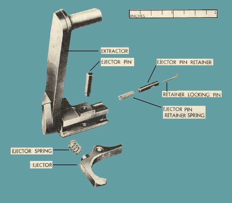
Figure 87. Extractor Assembly - Exploded View.
(1) Depress the ejector pin retainer as far as it will go.
(2) Using a small drift, work out the hooked end of the retainer locking pin from the hole in extractor, and remove the pin, retainer, and spring.
Caution: Be careful that retainer and spring do not fly out.
c. Do not attempt to disassemble the driving spring rod with springs assembly. Bent or damaged rod with springs, which bind in the bolt, will be replaced.
95. Inspection.
a. With backplate assembly aud driving spring rod with springs assembly removed from gun, operate bolt backward and forward by hand to ascertain thnt it slides freely.
b. Check bolt assembly for chipped T-slo't, cracks, and battered rear face.
c. Sear and sear slide must work smoothly in the guide cuts in the bolt without tendency to bind or stick. Engaging notch on the sear must have a fine mirror finish. Angle must be sharp without a feathered and battered edge.
d. Check cocking lever pin and locking pin for battering of mating surfaces.
e. Bolt switches should be flush with walls of boltways.
f. Check firing pin and firing pin extension assembly assembled for free movement in bolt. It must not bind.
b. Inspect extractor assembly for deformation, wear, and burs, with particular attention given to the tear-drop shaped lug on side of extractor.
96. Repair.
a. Replace all broken, badly worn, or otherwise unserviceable parts.
b. Remove all burs and rust from components (par. 82a and b).
97. Assembly and Installation.
a. Assemble extractor assembly (fig. 87) as described in (1) through (3) below.
(1) Insert ejector pin retainer spring in hole in side of extractor.
(2) Insert retaining locking pin and ejector pin retainer in hole in side of extractor.
Note. Position retainer so that ejector pin engaging notch is toward bottom of extractor. Also position retainer locking pin so that hooked end is pointing up,
(3) Depress retainer as far as it will go. Engage hooked encl of locking pin in small pinhole in extractor.
b. Assemble and install bolt group as outlined in paragraphs 59 and 60.
98. Removal and Disassembly.
a. Remove and disassemble barrel buffer group as instructed in paragraphs 62 and 63.
b. To disassemble barrel buffer assembly, using oil buffer remover tool 7319903 (figures 86 and 88), proceed as outlined in (1) through (4) below.
(1) Set the knurled knob of the tool so that the stop pin is in a vertical position.
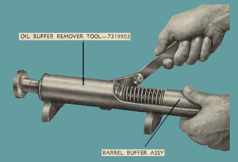
Figure 88. Remove barrel buffer spring and guide assembly, using oil buffer remover tool - 7319903.
(2) Place the barrel buffer a:sembly in the tool in such a position that the notch in the buffer piston rod alines with the shaft notch in tool. In this position, with the notch in the buffer piston rod engaged with the notch on shaft of tool, compress the buffer spring by moving the handle fully forward.
(3) Turn the knob on th tool one-fourth turn to the left, alining the piston rod with th slots in the guide assembly.
(4) Return the tool handle to allow the spring to expand and free the spring and guide assembly from the piston rod.
c. Remove buffer tube cap from barrel buffer tube and piston group by socuriug the group in a vise at the two milled notches at base of tube and unscrewing the cap.
d. Place the piston group in a vise and compress the buffer-washer spring group assembly until the barrel buffer piston pin (figure 89) can be pushed out freely. e. Remove the piston group from vise and disassemble the buffer piston rod, washer spring grour assembly, valve retainer, valve spring, and valve from the buffer piston (figure 90).
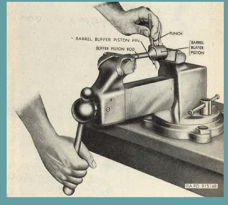
Figure 89. Removing barrel buffer piston pin.
99. Inspection.
a. heck all parts for burs, rust, foreign matter in recesses, deformation, and excessive wear, which may cause malfunction of the gun.
b. Check piston and inside of barrel buffer tube for roughness caused by burs. The piston must slide in the tube without binding.
c. Check piston rod for defon11ntioJ1 bnned notch, or loose pin.
d. Check barrel buffer body Spring lock for retention in buffer body.
100. Repair.
a. Replace all broken, badly worn, or otherwise unserviceable parts.
b. Remove all burs and rust from omponents (pars. 82a and b).
c. Replace buffer valve, valve spring, and valve retainer if these parts are corroded.
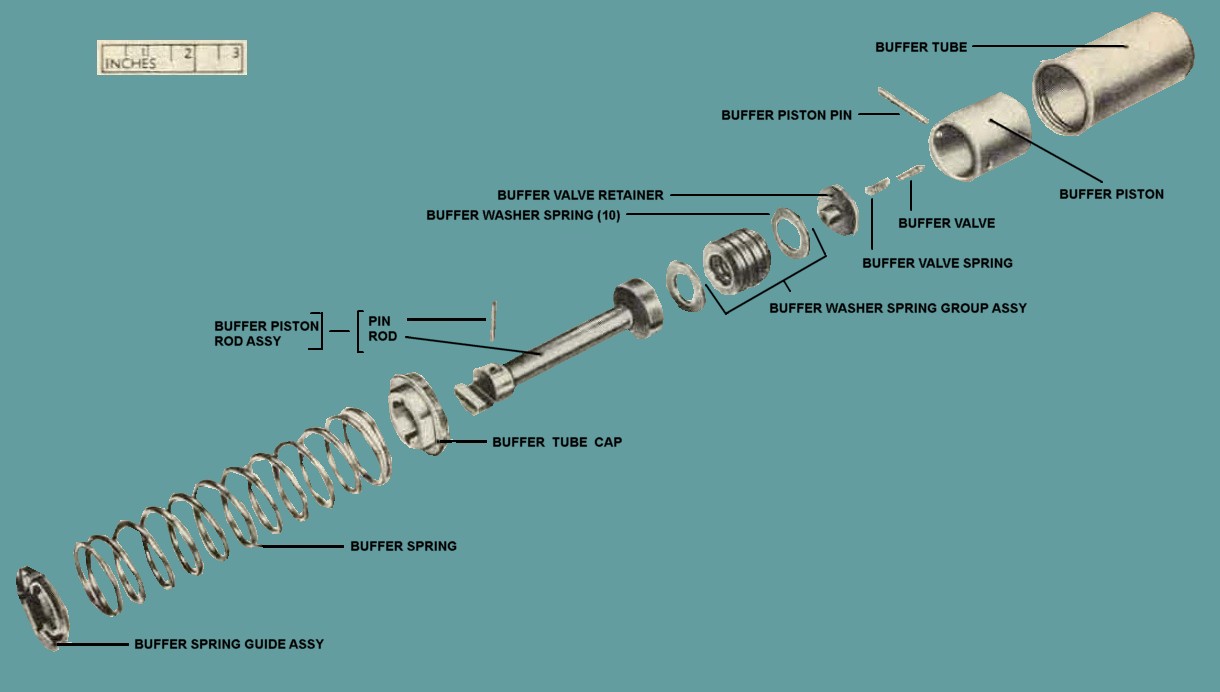
Figure 90. Barrel buffer group - exploded view.
101. Assembly and Installation.
a. Prior to assembling the barrel buffer assembly, the inside of the buff er tube and piston should be thoroughly cleaned, dried, and then oiled with a cloth lightly moistened with special preservative lubricating oil.
Note. No oil is to be used if guns are to be subjected to extremely low temperatures (pars. 33, 34 and 64). Insert the buffer valve spring and buffer valve retainer inside the buffer piston, with the nose of valve resting in piston opening (figure 90).
b. Insert buffer washer springs (fig. 90) into piston in pairs with convex sides facing.
Note. Make certain the end springs have the concave sides to the outside.
c. Position the buffer piston rod assembly into position so that holes in rod and piston (figure 89) are in alinement, and compress the washer springs by clamping the piston group in a vise until the buffer piston can be inserted. Make sure that ends of pin are flush with surface.
d. Insert the piston group into the buffer tube, making certain that the piston slides freely the entire length of tube.
e. Secure the buffer tube in a vise at the two milled notches on the tube, and screw on the buffer tube cap securely. Stake cap into notch in tube to prevent loosening.
f. Assemble barrel buffer spring, using oil buffer remover tool 7319903 (figure 86), as indicated in (1) through (3) below.
(1) Insert the guide assembly into the tool, locating the three guide lugs with the slots in tool.
(2) Set the knurled knob on the tool so that the stop pin is in a vertical position, and insert the buffer spring and barrel buffer tube and piston group in the tool in such a position that the notch in buffer piston rod alines with notch in tool shaft when the buffer spring is compressed.
(3) Compress buffer spring by operating the tool handle fully forward. With spring compressed, turn knurled knob on tool one-fourth turn, seating the piston rod pin in the retaining grooves in the guide.
g. Assemble and install barrel buffer group as outlined in paragraph 65.
102. Removal and Disassembly.
Remove and disassemble barrel and barrel extension group as outlined in paragraphs 68 and 69.
103. Inspection.
a. Inspect barrel extension for burs, nicks, and rust.
b. Check for distortion in the extension shank or for excessive wear and battering.
c. Check barrel extension threads for excess looseness when screwed in barrel.
d. Check breech lock slot, breech lock camways, and boltways for excessive wear.
e. Inspect barrels for wear of bullet seat and riflings. Barrels that are unserviceable contain liners tha.t have a substantial quantity of valuable material and will be disposed of as described in (1) through (3) below.
(1) Barrels should be cut off 14 inches from the breech end. Cutting may be accomplished by any available means, such as shearing, cutting wheel, or cutting torch. The dimension, 14 inches, is approximately 1½ inches beyond the encl of the liner to prevent squeezing the liner in the tube by shearing and/or welding the liner to the tube with the cutting torch.
(2) The breech (rear) end of the barrel will "then be shipped to Springfield Armory for salvage of the liner.
(3) The alternate method ( (a) through (d) below) of salvaging liners is furnished for information to those installations having adequate heating facilities.
(a) Heat barrel or barrel section, cut to a convenient size for handling, insert in furnace 1,700° to 1,800° F., and hold for 1 hour at that temperature.
(b) Remove from furnace and quench in water (container should be at least 5-gal. cap).
(c) Break barrel open by impact and remove liner.
(d) Steps (a) and (b) above cause the barrel to crack lengthwise. The barrel or barrel section may be broken by dropping from a height of 4 feet or more onto a suitable surface such as a 12 x 12 x 1 steel plate, 3-inch square bar, or hitting the section with a sledge hammer.
104. Repair.
See paragraph 70 for repair.
105. Assembly and Installation.
Assemble and install barrel group as outlined in paragraphs 71 and 72.
106. Removal and Disassembly.
a. With cover open, remove cotter pin from cover pin. Drift out cover pin from receiver.
b. Rotate cover group upward and forward to remove cover group from trunnion block (figure 79).
c. Disassemble cover group as outlined in paragraph 74.
d. Remove belt feed pawl arm locating plunger, by driving out locking pin from pawl.
Caution: Be careful plunger and spring do not fly out.
107. Inspection.
a. Check extractor cam for wear, burs, fractures, or loose rivets.
b. Check cover latch for fracture or burs.
c. Check belt feed lever for fracture, deformation, and free movement on pivot stud and slide when assembled. Check lugs for wear and burs.
d. Check belt feed pawl for burs. Check to see if correct belt feed pawl nsse.rnuly is used (par. 75).
e. Check operation of cover detent pawl. It should hold cover open in three positions.
f. Check operation of cover latch; ascertain that cover latch spring has sufficient tension to keep cover securely latched.
g. Check cove extractor spring stud and cover latch spring stud for loosenes; if loose, notify ordnance maintenance personnel.
h. Check cover extractor spring retainer (alternate desigu covers) for looseness and ability to retain extractor spring. If it must be replaced, not1fy ordnance maintenance personnel.
108. Repair.
a. Replace all broken, badly worn, or otherwise miserviceable parts.
b. Remove all burs and rust from components (par. 82a and b).
c. For loose extractor cam rivets, notify ordnance maintenance personnel.
d. When cover is fitted to the receiver, the cover latch must be fitted to the top plate notch. No metal should be removed from the top plate. Clearance between the cover latch and notch in top plate must not exceed 0.010 inch measured with a feeler gage (figure 91).
109. Assembly and Installation.
a. Assemble cover group as outlined in paragraph 76.
b. Place belt feed pawl arm locating spring in its well on the pawl and press the plunger over the spring. Aline the notch in the plunger with pinhole in pawl and insert locking pin. Be sure plunger functions smoothly and both ends of locking pin are flush with surfaces of pawl.
c. To install cover group on the receivor, p1ace latch end of the cover in position, with the latch engaging top plate.
d. Force the hinge and downward in position. Use a driftpin to secure alinement of the pinholes in cover and receiver.
e. Insert cover pin and new cotter pin. Make sure cotter pin is bent, so that ends cannot interfere with feeding of ammunition.
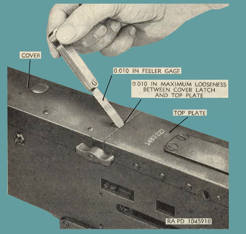
Figure 91. Measuring cover latch clearance.
110. Disassembly.
a. Disassemble receiver and recoil booster as outlined in paragraph 78.
b. To disassemble recoil adaptor assembly from receiver (if assembled), see applicable Air Force technical orders.
Note. When returning guns to ordnance for rebuild, the recoil adapter should be removed and returned to stock.
c. Barrel jacket with recoil booster assembly should not be disassembled unless damage, defective, or unserviceable. To disassemble, remove the breech bea.ring lock screw from top of tnnmion block (figure 79) that secures the barrel jacket to the trunnion block.
d. Unscrew the barrel jacket from receiver.
e. Remove cotter pin from trunnion block lock and remove lock and spring (figure 79).
111. Inspection.
a. Check all parts for burs, rust, foreign matter in recesses deformation, and excessive wear, which may cause malfunction of gun.
b. Check top, bottom, and side plates for cracks or deformation. Receiver must not be bulged or bent. The total clearance between bolt and side plate, with bolt in battery position and measured at rear of bolt, should be between 0.012 and 0.024 inch.
c. Check belt holding pawl brackets for cracks.
d. Check receiver for loose rivets. Check for loose breech lock depressor rivets and extractor cam rivets.
e. Examine cover detent pawl and trunnion block lock for burs. Pawl and lock should operate without binding inside the trunnion block.
f. Check barrel jacket for deformation, rust, and dents. Dents and deformation will cause the barrel to bind in jacket or prevent the recoil adapter assembly from sliding over the jacket during assembly.
g. Check recoil booster for tightness, burs, and rust.
h. Check link chute adapter assembly for cracks or looseness.
i. Check link chute adapter positioner for operation.
j. Check breeck lock cam for clearance (par. 80) .
k. Check cleanmce of 0.002 inch between top plate bracket, and bolt.
112. Repair.
a. Replace broken, worn, or otherwise unserviceable parts. Remove burs and rust from components (par. 82a and b).
b. Receiver group will be tagged for rebuild by ordnance maintenance personnel upon evidence of loose rivets.
c. If the riveted-type bracket is used and required clearance of 0.002 inch does not exist, attempt to correct by changing bolt. If the above methods do not provide the correct clearance, notify ordnance maintenance personnel.
113. Assembly.
a. Screw the barrel jacket on the receiver and tighten until holes for breech bearing lock screw are in alinement.
b. Secure the barrel jacket to the trunion block by replacing the breech bearing lock screw.
c. If new jacket is being assembled, tighten jacket firmly as instructed in "a" above and drill a hole (No. 7 drill) in the barrel jacket for the breech bearing lock screw.
Caution: Do not damage screw threads in trunnion block.
d. Install trunnion block lock spring ancl lock in bottom of trunniun block. Depress lock and secure with new cotter pin.
Note. Spread cotter pin sufficiently for retention but do not bend it around lock. Pull the trunnion block lock to the rear and turn it one-fourth tum, so that it is retained to the rear.
e. To replace recoil adapter assembly on receiver, see applicable Air Force technical orders.
Note. Trunnion block shims are not required when recoil adapter assembly is used.
f. Assemble receiver and barrel jacket group as outlined in paragraph 80.
114. General.
Guns turned in for repair have defects caused by use or neglect. When they were accepted as new guns, their component parts were dimensionally correct and made of proper material. Consequently, the inspection of guns after repair will differ t from the inspection prcedure used in manufacture iu that attention is directod to wearing surfaces, parts that might crack or break due to high stress or fatigue, and indications of corrosion. These defects do not evidence themselves by uniform reduction in a given dimension but appear as a chipped edge, a partially worn surface, or an eccentric hole. After a pitrt is worn through use, th chiuig in dimension is easily detected in many cases by comparing with adjacent surfaces or the corresponding portion of a new part.
115. Visual Inspection.
a. Guns will be inspected visually for the following:
(1) General appearance, smoothness of operation, and completeness.
(2) Fit of cover in closed position and operation in open position.
(3) Barrel must be straight, clean, free of rust, and free of bulges and rings. Fine pitting is allowable.
(4) Barrel jacket and trunnion adapter and/or recoil booster is assembled £or looseness.
(5) Backplate assembly for binding in receiver.
(6) Backplate latch for retention of backplate.
(7) Bolt group and barrel extension group for binding in receiver. Check clearance between bolt and side plate as outlined in paragraph lllb.
(8) Loose link chute adapter assemb]y.
b. After guns have been repaired and assembled, they will be checked for proper Operation as outlined in (1) and (2) below.
(1) Check head space and timing (pars. 14 and 15).
(2) Check fonctioning of machine gun by hand- or function firing (par. 116).
116. Function-Firing.
a. After guns have been repaired and assembled, guns should be function-fired. Barrels considered worn beyond serviceability limits (slave barrels) should be used if possible. Guns that fail to meet the function-firing test are to be corrected by replacemet of component or such other repair as caused by the malfunction (table III and table VI).
b. The gun should be mounted in a suitable stand (figure 92) with sufficient clearance beneath the gun to prevent ejected cartridge cases and links from piling up. The gun must be capable of lifting a 35 pound weight that is attached by suitable means to the end of a belt suspended over a pully in such a manner that the belt extends horizontally from the feedway. A belt feed test spring is placed between the weight and the belt.
c. Mount a solenoid on the gun and connect to a 24-volt direct current supply. A firing switch is to be hooked in series with the solenoid. Load into the gun an ammunition belt containing 10 live rounds and 2 dummy rounds, with the live rounds leading. Repeat this procedure for other side.
d. If gun fails to fire 10 rounds, check the following components.
(1) Belt feed pawl assembly.
(2) Belt feed pawl springs.
(3) Belt holding pawl springs.
(4) Belt feed lever.
117. Return to Ordnance for Rebuild.
Guns returned to ordnance for rebuild must be inspected for compliance with the requirements given in "a" through "c" below.
a. AF Form 185 must be complete and accompany weapon as prescribed in AFR 136-5.
b. The Edgewater adapter must be removed and returned to stock prior to returning gun for rebuild.
c. Weapon must be complete. All deficiencies will be reported on AF Form 185 and substantial reasons
for the deficiencies noted.
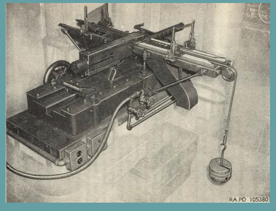
Figure 92. Gun in function-firing stand with 35-pound weight attachd to cratridge belt.
118. General.
The information in this section, pertaining to the several types of cartridges authorized for use in this machine gun, includes a description of the cartridges, means of identification, care, use, and ballistic data. Detailed information pertaining to small-arms ammunition is contained in TM 9-1990.
119. Classification.
a. Based upon type of bullet and use, the ammunition for this machine gun is classified as armor-piercing, armor-piercing-incendiary, armor-piercing-incindiary-tracer, ball, incendiary, tracer, headlight tracer, and dummy.
b. Armor-piercing cartridges are for use against armored aircraft and lightly armored vehicles, concrete shelters, and other bullet-resisting targets. The bullet consists of three parts: a gilding metal jacket, a hardened core of tungsten-chrome or manganese-molybdenum steel, and a point filler of an antimony-lead alloy. The overall length of the bullet is 2.31 inches.
c. Armor-piercing-incerrcliary cartridges are for use against targets where the armor-piercing and incendiary effects are both desired. The bullet is similar to the armor-piercing bullet, except that the point filler is replaced by an incendiary composition. The length of the bullet is 2.31 inches for the API cartridge M8 and is 1.935 inches for the API cartridge T49.
d. Armor-piercing-incendiary-tracer cartridges are for use as in "c" above, with the tracer added to reveal the path of the bullet.
e. Ball cartridges are for use against personnel and light material targets. The bullet consists of three parts : a gilding metal jacket, a soft steel core, and a point filler of an antimony-lead alloy. The overall length of the bullet is 2.31 inches.
f. Incendiary cartridges are for use against flammable targets, especially fuel and oil systems on aircraft and vehicles. The bullet consists of a gilding metal jacket, a hollow cylindrical steel body, a leadantimony base slug, and a core and point filler of incendiary composition. The bullet is 2.35 inches long.
g. Tracer cartridges are used to reveal the path of the bullet. Secondary purposes are for incendiary effect and for signaling. The bullet consists of three parts: a gilding metal jacket or a gilding metalclad steel jacket, a hardened lead slug that fills the forward end of the jacket, and tracer and igniter compositions that fill the balance. Unlike the bullets for the armor-piercing and ball cartridges, this bullet. is cylindrical to the base. The base is open to permit the propelling charge to ignite the tracer composition.
h. Headlight tracer cartridges are similar to tracer cartridges except that the trace is appruximutely three times more brilliant when viewed from the front than the tracer cartridge described in "g" above.
i. Dumny cartridges are for use in training. They may also be used for testing the mechanism of the gun. The bullet consists of a gilding metal jacket or gilding metal-clad steel jacket only. The bullet is 2.40 inches long and has a cylindrica1 base.
120. Identification.
a. General.
The marking on all original packing containers, both boxes and cartons, clearly and fully identifies the ammunition except as to grade; for grade, see "f" bellow. The significance of the AIC (Ammunition Identification code) symbol and silhoute as part of the marking is explained in "g" below. The ammunition lot number, including its importance, is desribed in "d" and "e" below. The cartridges themselves, are marked and stamped ss indicated in (1) and (2) be1ow.
(1) The manufacturer's initials or symbol and the year of loading are stamped on the base of the cartridge case.
(2) The distinguishing characteristics of the several types and models of cartridges are described in "b" below.
b. Types.
When removed from their original packing containers, the cartridges may be identified, except as to ammunition lot number and grade, by physical characteristics described below and illustrated in figures 93 through 96. Care should be taken not to confuse these original markings on the bullets with any subsequent markings made with coloring material which is used to identify gunner's hits during target practice (h below).
| NUM | TYPE | DISTINGUISHING CHARACTERISTICS |
| 1 | Armor piercing | Tip of bullet painted black. |
| 2 | Armor-piercing incendiary MS. | Tip of bullet painted aluminum color. |
| 3 | Armor piercing incendiary T49. | Tip of bullet painted Blue, with aluminum color annulus to the rear. |
| 4 | Armot piercing incendiary - Tracer. | Tip of bullet painted red, with aluminum color annulus to the rear. |
| 5 | Ball | Copper-colored gilding metal jacket on bullet (no markings) |
| 6 | Incendiary M1 | Tip of bullet painted blue. |
| 7 | Incendiary M23 (T48) | Tip of bullet painted blue, with light blue annulus to the rear. |
| 8 | Tracer M1 and headlight tracer M21 (T1E1). | Tip of bullet painted red. |
| 9 | Tracer M10 | Tip of bullet painted orange. |
| 10 | Tracer M17 (T9) | Tip of bullet painted maroon. |
| 11 | Dummy | Three (or two in some cases) holes are drilled in the body case; the primer pocket is empty. In addition, older lots may have tinned cases. |
| |
c. Model.
To identify a particular design, a model designation is assigned at the time the item is classified as an adopted type. This model designation becomes an essential part of the standard nomenclature of the items and one of the means of identification. The present system of model designation consists of the letter M followed by an Arabic numeral; for example M2. Similarly, a system applied to dcvelopment items involves the use of a T designation to indicate the basic design and an E to indicate modifications threof. Thus TlEl would indicate Lhe list. modification of a development item originally designed Tl.
d. Ammunition lot Numbers.
When ammunition is manufactured, an ammunition lot number, which becomes an essential part of the marking is assignedin accordance whith pertinent specifications. This lot number, or the repacked lot number (e below), is marked on all packing containers. It is required for all purposes of record, including grading and use, reports on condition, functioning, and accidents in which the ammunition might be involved. No lot other than that of current grade appropriate for the weapon will be fired (f below). Sincc it is impractical to mark the amnnmition lot number on each individual cartridge, every effort should be made to maintain the ammunition lot number of cartridges that are removed from their origina1 pnckings. Cartridges for which the ammunition lot number has been lost are placed in grade 3 (unserviceable ammunition that will not be issued or fired); therefore, wheu cartridges are removed from the original packings, they should be marked or tagged so that the ammunition lot number may be preserved. The letter S preceding the serial number of an ammunition lot indicates that the cartridge case is made of steel. Rounds of ammunition assembled with steel cartridge cases are authorized for all training requirements only.
e. Replaced Lot Number.
(1) Since ammunition in metallic-link belts (figure 97) may consist of more than one type of cartridge and hence would require two or more lot numbers marked on each packing box and in records, a single repacked lot number is assigned by the repacker to replace the origina1 amunition lot numbers. This repacked lot number is marked On one side, ou 0ne end.
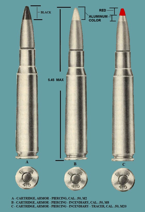
Figure 93. Cal. .50 cartridges - AP, API, and API-T.
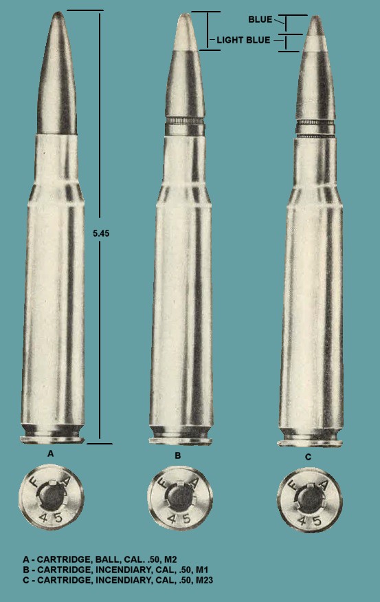
Figure 94. Cal. .50 cartridges - Ball and incendiary.
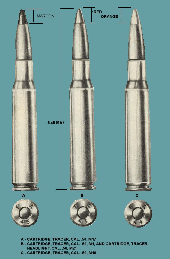
Figure 95. Cal. .50 cartridges - Tracer.
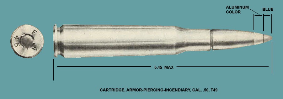
Figure 96. Cal. .50 cartridges - API, T49.
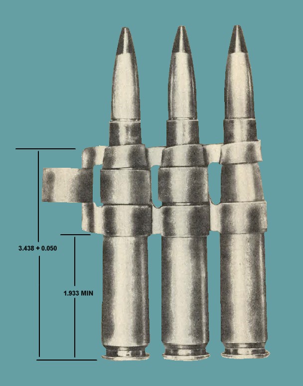
Figure 97 Proper positioning of cartridges in link.
and on the top of each packing box. The ammunition lot numbers of the cartridges cornprising a repacked lot nre listed on the reference card placed inside the packing box.
(2) The repacked lot number c011sists of the words REPLACED LOT, the initials of the repacker, the letter L for linked cartridges, and the lot number assigned by the repacker.
f. Grades.
Small-arms ammunition is graded primarily on the qualities that make the lot especially suited for use in a particular class of weapous; :for example, a lot of ammunition assigned grade AC is especially suited for use in aircraft weapons. Current grades of all existing lots of small-arms ammunition are established by the Chief of ordnauce nnd are published in TB 9-AMM 4. Only those lots of appropriate grade will be fired. Grade 3 indicates unserviceable ammunition that will not be issued or fired; however, ammunition placed in grade 3 due to loss of ammunition lot number, but which can be identified as having been in serviceable lots issued to a specific organization, may be reissued after visual inspection, but only for local training purposes in ground machineguns.
g. Marking.
In addition to the required markings on packing boxed for shipping purposes, the information given in (1) through (4) below is also stenciled or marked on the boxes (figs. 08--100).
(1) Ammunition lot number or repacked lot number.
(2) Types and ratio of the cartridges within the box; or type only, if all of one type; for example, "4 BALL M2, 1 TR Ml" or "AP."
(3) Silhouettes on one side and one end of the larger packing boxes containing cartridges in web belts and linked belts to indicate the type of inner packing; for example, :for cartridges packed in metallic-link belts, the silhoneUe shown in figure 98 is used. However, the smaller boxes of linked ammunition do not have sufficient space for the silhouette (see figure 100). Ammunition packed in cartons does not, have silhouettes regardless of size of box. For cal. .30 cartridges, the silhouettes of web and linked belts are vertical; for cal. .50 cartridges, they are diagonal.
(4) AIC symbols as published in Department of the Army supply manual ORD 3 SNL T-1. These ATC symbols inclicate a specific cartridge, or combination of cartridges, having a specific grade and packing.
h. Coloring bullet Tips.
The number of hits made upon a target by a certain machinegun or group of machinegnns when others are firing upon the same target is sometimes determined by coating the tips of bullets with coloring material. The bullets from each weapon or group of weapons are coated with a distinctive color, which upon striking the target leaves a colored smear indicating the weapon from
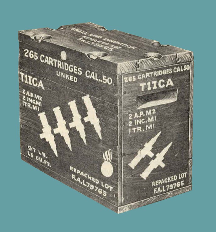
Figure 98 Packaging box M1917 containing cal. .50 linked cartridges.
which fired. For the method of application, see TM 9-855. Cartridges that have been so coated must have the coloring removed before retnrn to storage.
121. Care, Handling, and Preservation.
a. General. (1) Ammunition is packed to withstand conditions ordinarily encountered in the field. Small arms ammunition: as compared with other types of ammunition, is not dangerous to handle. Care, however, mnst be observed to keep packings from becoming broken or damaged. All broken packings must be repaired immediately and careful attention given to the trnnsfer of all markings to the new parts. If the hox contains a metal liner, it should be air-tested and sealed, provided that equipment for this work is available.
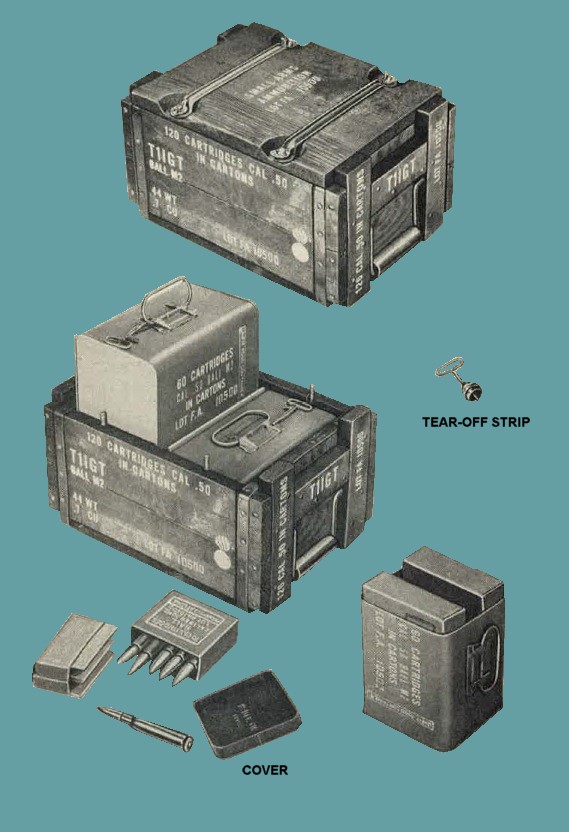
Figure 99 Packaging box M12 containing cal. .50 cartridges in cartons in metal cans M10.
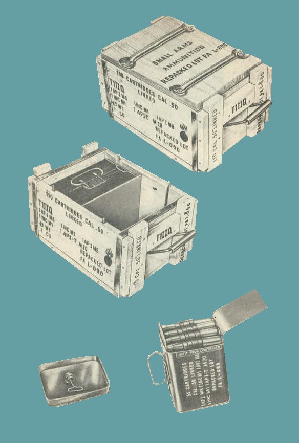
Figure 100 Packaging box M12 containing cal. .50 link cartridges in metal cans M10.
(2) Ammunition boxes should not be opened until the ammunition is required for use. Ammunition removed from its container, particularly in damp climates, is apt to corrode, thereby rendering the ammunition unserviceable.
(3) The ammunition should be protected from sand, mud, frost snow, ice, oil, grease or other foreign matter. If it gets wet or dirty, it should be wiped off at once. If verdigris or light corrosion forms on cartridges, it should be wiped off with a clean, dry cloth; however, cartridges should not be polished to make them look better or brighter.
(4) The use of oil or grease on cal. .50 cartridges is prohibited.
(5) Ammunitiou should not be exposed to the direct rays of the sun for any 1ength of time. Such exposure may seriously affect its firing qualities.
(6) Whenever cartridges are taken from original packing containers, they will be tagged or otherwise marked so that the ammunition may be identified as to lot number. Such identification is necessary to prevent otherwise serviceable ammunition from being placed in grade 3 through loss of ammunition lot number.
(7) Rounds not fired will be returned to their original condition and packing and be appropriately marked. Such rounds will be used first in subsequent firings in order that stocks of opened packings may be kept to a minimum.
b. Storage.
(1) Whenever practicable, small arms ammunition should be stored under cover. This applies partially to tracer ammunition, which is subject to rapid deterioration if it becomes damp and may even ignite spontaneously. When it is necessary to leave small arms ammunitiou in the open, raise it on dunnage at least 6 inches from the ground and cover it with a double thickness of paulin, leaviug enough space for the circulation of air. Where practicable, dunnage strips should be placed under each layer of ammunition boxes. Suitable trenches should be dug to prevent water from running under the pile.
(2) Ammunition, when stored, should be segregated by type and ammunition lot number (see TM 9-1900).
(3) In a fire, small arms ammunition does not explode violently. There are small individual explosions of cartridges, the case flying in one direction and the bullet in another. It is unlikely that the bullets or cases will fly over 200 yards.
(4) Small arms ammunition in storage should be protected from extreme heat in order to avoid decomposition of the propellent powder and the tracer mixture in tracer ammunition. The combination of high temperatures and a humid atmosphere is particularly detrimental to the stability of the powder and the tracer mixture.
(5) When only a part of a box of ammunition is used, the ammunition remaining in the box should be protected against unauthorized handling and use by firmly fastening the cover in place.
122. Authorized Rounds and Ballistic Data.
a. Rounds.
The ammunition (par. 120b and figs. 93-96) of appropriate grade (par. 120f) is authorized for use in this machinegun. It will be noted that the nomenclature (standard nomenclature) completely identifies the cartridge as to type, caliber, and model. Links authorized for separate issue are also listed in table VII. Cartridges that are issued in metallic-link belts are listed in Department of the Army Supply Manual ORD 3 SNLT-1.
b. Ballistic Data.
The maximum ranges, muzzle velocities, weights of rounds, and times of flight to 1,000 yards of the service types of cal. .50 ammunition authorized for use in this machinegun are given in table VII. The trajectories of these cartridges cross at 1,000 yards. Terminal ballistic data appear in TM 9-1907.
c. Penetration.
Armor-piercing bullets will penetrate 7/8-inch homogeneous armor plate at 100 yards at normal impact and 5/8-inch face hardened armor plate at 100 yards at 30 degrees impact.
Table VII. Authorized rounds for cal. .50 Basic Aircraft Machine Gun AN-M3.
| Standard Nomenclature | Average muzzle velocity (fps) | Time of flight to 1,000 yards (sec) | Elevation (deg) | Maximum range (yds) | Weight (lbs) |
| CARTRIDGE, Armor piercing cal. .50, M2 | 2,840 | 1.38 | 35 | 7,275 | 0.26 |
| CARTRIDGE, Armor piercing - incendiary, cal. .50, M8 | 2,950 | 1.40 | 30 | 6,375 | .25 |
| CARTRIDGE, armor piercing - incendiary, cal. .50 T49 | 3,450 | ----- | 30 | 5,500 | .23 |
| CARTRIDGE, armor piercing - incendiary tracer, cal. .50 M20 (T28)b | 2,950 | 1.40 | 30 | 6,375 | .24 |
| CARTRIDGE, ball, cal. .50 M2 | 2,840 | 1.38 | 35 | 7,275 | .26 |
| CARTRIDGE, incendiary, cal. .50 M1 | 2,990 | 1.36 | 35 | 5,960 | .24 |
| CARTRIDGE, incendiary, cal. .50 M23 (T48) | 3,450 | ----- | 30 | 5,500 | .23 |
| CARTRIDGE, tracer, cal. .50 M1 od | 2,730 | 1.37 | 30 | 5,470 | .25 |
| CARTRIDGE, tracer, cal. .50 M1 (alternative) od | 3,450 | ----- | 30 | 5,500 | .23 |
| CARTRIDGE, tracer, cal. .50 M1 od | 2,730 | 1.37 | 30 | 5,470 | .25 |
| CARTRIDGE, tracer, cal. .50 M10 * | 2,900 | 1.37 | 35 | 5,350 | 0.25 |
| CARTRIDGE, tracer, cal. .50 M17 (T9) f | 2,900 | ----- | 35 | 5,350 | .25 |
| CARTRIDGE, tracer, headlight, cal. .50 M21 (T1E1) * | 2,900 | ----- | 35 | 5,350 | .25 |
| CARTRIDGE, tracer, headlight, cal. .50 M21 (alternative) * | 2,730 | ----- | 30 | 5,470 | .25 |
| CARTRIDGE, dummy, cal. .50 M2 | 2,900 | ----- | 35 | 5,350 | .25 |
| LINK, metallic belt, cal. .50 M2 | ----- | ----- | ----- | ----- | .18 |
| LINK, metallic belt, cal. .50 M1 | ----- | ----- | ----- | ----- | .038 |
| LINK, metallic belt, cal. .50 M2 | ----- | ----- | ----- | ----- | .038 |
| LINK, metallic belt, cal. .50 M9 (T43) | ----- | ----- | ----- | ----- | ----- |
| LINK, metallic belt, cal. .50 T31E2 | ----- | ----- | ----- | ----- | ----- |
| LINK, metallic belt, cal. .50 T31E3 | ----- | ----- | ----- | ----- | ----- |
| |
AN-Army-Navy.
cal.-caliber.
deg-degree (angle).
fps-feet per second.
lb-pound(s)
sec-second(s).
yd-yard(s).
• In 36-inch barrel.
b Dim trBce to 300 yards and bright trace to 1,750 yards.
• Trace to 1,800 yards.
d Limited to use for .training purposes only.
• Dim trace to 226 yards and bright to 1,900 yards.
t Trnce to 2,450 yards.
• Brilliant trace to 550 yards, visible from target
123. Precautions in Firing.
a. Ammunition that is seriously corroded should not be fired.
b. Cartridges that have been seriously damaged should not be fired, for example, those that have a badly dented or scratched case or a loose bullet.
c. No cal. .50 ammunition will be fired until it has been positively identified by ammunition lot number and grade as published in the latest revision or change to TB 9-AMM 4.
d. Do not fire cartridges with oil or grease on them without first removing oil or grease with a clean, dry cloth or those that have become overheated due to exposure to the direct rays of the sun or other sources of high temperature. Such cartridges, if fired, may develop hazardous chamber pressures.
e. Misfires will be handled as indicated in paragraph 19e and SR 385-310-1, AFR 50-13.
124. Packing
Cal. .50 service cartridges are packed as indicated in table VIII and as illustrated in figures 98 through 100. The weights shown may vary slight1y, dependent upon the particular type of cartridge. For additional packing data. See Department of the Army Supply Manual ORD 3 SNL's T-1 and T-5.
Table VIII. Packing data for cal. .50 Ammunition.
CARTRIDGES
| Num | Packing | Volume (cu ft) | Weight (lb) |
| |
|||
| 1 |
Packed 10/ctn, 6 ctn/mtl can, M10, 2 can (120 round)/wdn bx, Ml2:
Dimensions of box: 14 1/4 x 10 1/4 x 7 1/2. |
0.7 | 44 |
| |
|||
| 2 |
Packed 10/ctn, 10 ctn/metal box, M2, 2 box (200 rd)/wrbnd box.
Dimension of box: 14 1/4. |
.9 | 67 |
| |
|||
| 3 | Packed 10/ctn, 10 ctn/metal box, M2, 2 box (200 rd)/mtl-lnd wooden box, M1917 | 1.5 | ----- |
| |
|||
| 4 |
Dimensions of bx: 18),~ x 9¼ x 14Jt
Packed 10/ctn, 12 ctn/metal can, M21, 2 can (240 rd)/wooden box, M23 Dimensions of box: 15 1/8 x 13 1/4 x 11 1/8. |
1.3 | 82 |
| |
|||
| 5 |
Packed 10/ctn, 12 ctn/waxed cntr, T2, 2 cntr (240 rd)/wooden box, T2 *
Dimensions of box: 15 1/4 x 14 x 9 1/8. |
1.1 | 79 |
| |
|||
| 6 |
Packed 10/ctn, 25 carton (250 rd)/mtl-lnd wooden box
Dimensions of box: 22 1/4 x 10 1/4 x 7 1/4. |
.9 | ----- |
| |
|||
| 7 |
Packed 10/ctn, 35 ctn (350 rd)/mtl-lnd wooden box, Ml9l7
Dimensions of box: 18 1/2 x 9 1/2 x 14 7/8. |
1.5 | 112 |
| |
|||
| 8 |
Packed 10/ctn, 6 ctn/metal can, MlO, 6 can (360 rd)/metal box, Mk 1 M1917.
Dimensions of bx: 18 5/8 x 9 5/8 x 15 1/8. |
1.5 | 127 |
| |
METALLIC-LINK BELTS
| Num | Packing | Volume (cu ft) | Weight (lb) |
| |
|||
| 1 |
Packed 55/belt, 1 belt/mtl can, MlO, 2 can (llO rd)/wdn bx, Ml2
Dimensions of bx: 14 1/4 x 10 1/8 x 7 7/8 |
0.7 | 43 |
| |
|||
| 2 |
Packed 60/belt, 1 belt/wxd cntr, 4 cntr (240 rd)/mtl-lnd wdn box, M1917 b.
Dimensions of box: 18 1/2 x 9 1/2 x 14 7/8. |
1.5 | 95 |
| |
|||
| 3 |
Packed 100/belt, 1 belt/metal box, M2A1 (T37), 2 box (200 round) / wrbnd box.
Dimensioos of box: 14 7/8 x 12 3/4 x 8 1/8. |
0.9 | 75 |
| |
|||
| 4 |
Packed 105/belt, l belt/metal box, M2, 2 box (2l0 rd)/wrbnd box.
Dimensions or box: 14 7/8 x 13 x 8 3/8. |
.9 | 84 |
| |
|||
| 5 |
Packed 112/belt, 1 belt/can, M21, 2 can (224 round)/wooden box, M23
Dimensions of bx: 15 1/8 x 13 1/4 x 11 1/8. |
1.3 | 83 |
| |
|||
| 6 |
Packed 265/belt, l belt (265 round)/metal-lnd wooden box, Ml017.
Dimeusions of box: 18 1/2 X 9 1/2 X 14 7/8. |
1.5 | 100 |
| |
bx-box.
cr--crate.
cntr-container.
ctn-carton.
cu ft-cubic foot.
lb-pound(s).
Mk-mark.
mod-modification.
mtl-metal.
mtl-lnd-metal-lined.
rd-round.
wdn-wooden.
wrbnd-wirebound.
* Some packings exist with unwaxed containers.
* Some packings exist with unwaxed containers; others with waxed and unwaxed containers but no meta liner.
125. Shipping Instructions.
a. Domestic Shipping Instructions.
(1) Preparation.
When shipping the cal. .50 basic aircraft machineguns AN-M3 interstate or within the zone of interior, the officer in charge of preparing shipments will be responsible for furnishing weapons to the carriers for transport in a serviceable condition, properly cleaned, preserved, packaged, and packed as prescribed in paragraph 127.
Note. Personnel withdrawing weapons that have been packed with volatile corrosion inhibitor treated material (VCI) must not remove weapons from pack. However, the removable box end should be removed and contents slid out for paclrnging inspection. If the VCI pack has been damaged or broken, the weapon will be removed and processed, packaged, and packed as prescribed in paragraph 127.
(2) Army shipping documents. Prepare all Army Shipping documents accompanying freight in accordance with TM 38-705.
b. Oversea Shipping Instructions.
(1) Inspection.
Inspect weapons destined for oversea use, prior to shipment, to determine their completeness and serviceability. Replace any defective weapons.
Note. Weapons that are packed with VCI material must not be removed from pack for inspection. However, the removable box end of container should be detached and effectiveness of pnckaging inspected. If the VCI pacl{ has been damaged or broken, the weapon will be removed and processed, packaged, and packed as prescribed in paragraph 127.
(2) Preparation for shipment to ports. Prepare weapons destined to ports of embarkation for oversea shipment the same as prescribed for domestic shipment (par. 127).
126. Storage Instructions.
a. Limited-Storage lnstructions.
(1) Reoeiving inspections.
(a) Report on DD Form 6 all weapons received for storage in a damaged condition or improperly prepared for shipment, in accordance with SR 745-45-5. Report of weapons received in an unsatisfactory condition (chronic failure or malfunction) will be made on AF form 5,4 in accordance with SR 700-45-5.
(b) Immediately upon receipt, weapons that have not yet been inspected and prepared for limited storage must be given a limited technical inspection and processed, packaged, and packed as prescribed in paragraph 127. Results nnd classification will be recorded and packed with the weapon.
(c) Perform a systematic inspection and replace or repair all miissing or broken parts. If repairs are beyond the scope of the unit and will cause weapons to be out of service for an appreciable length of time, store them in a limited storage status and attach tags specifying repairs needed. Report, of these conditions will be submitted by the unit commander for action by an ordnance maintenance unit.
(2) Inspection during storage.
Perform a visual inspection periodically to determine genera1 condition. If corrosion is found, remove, clean and treat items with the prescribed preservatives.
Note. Weapons that have been packed with VGI material must uot be removed from pack for inspection. Howevur, the removalble box end of container should be detacbed and effecttveness of packaging inspected. If the VCI pack has been damaged or broken, the weapon will be removed, processed, packaged, and packed as prescribed in paragraph 127.
(3) Storage Site.
(a) Personnel must carefully note the storage site to determine whether location is adequate.
(b) Whenever possible, store weapons in a room where moisture content of Sir is kept at a low relative humidity (40 percent or less) and at an even temperature. When it is found necessary to store packages outdoors, cover and protect them against the elements as prescribed in TB ORD 379. (4) Rernoval from limited storage.
(a) If weapons are not shipped or issued upon expiration of the limited storage period, they must be further inspected and treated for standby or loug term storage as prescribed in "b" below.
(b) If weapons to be shipped will reach their destination within the limited storage period, they need not be reprocessed upon removal from storage, unless inspection reveals it to be necessary according to anticipated changing weather conditions.
Note. All weapons being reissued through the depot supply system to troops within the continental limits of the United States must meet the requirements of TB ORD 385. This is NOT required for so-called reissues, exchanges, or redistribution among troop units, where the de11ot supply system is not involved.
(c) Weapons will be serviced in accordance with paragraphs 6 through 11, when it has been ascertained that they are to be placed into immediate service. Lubricate weapons as prescribed in paragraphs 33 and 34.
(d) Repair and/ or replace all items tagged in accordance with (1) (c) above.
b. Standby and Long Term Storage.
(1) Maintenance in-storage inspection.
(a) Maintenance in-storage inspection must be performed by qualified ordnance maintenance personnel.
(b) Inspection of weapons will preferably be performed in an area expressly set aside for that purpose or in a maintenance shop, when such facilities are available.
Note. Weapons that have been packed with VCI material must not be removed from pack for percentage inspection. However, the removable end of container should be detached and effectiveness of packagiug Inspected. If the VCI pack has been damaged or broken, contents will be removed and processed, packaged, and packed as prescribed in paragraphs 127 and 128.
(c) Inspect at least 1 percent of weapons in storage semiannually. If results of the 1-percent inspection reveal defective weapons, then inspect 10 percent of the weapons. If additional defective weapons are discovered, then inspect entire lot and process, package, and pack in accordance with paragraph 127.
(d) When 1-percent or JO-percent inspection proves satisfactory, select weapons not previously inspected for the next inspection.
(2) Packaging. Inspectors must careful1y examine selected packages, observing the basic points listed below :
(a) Condition of containers.
(b) Legibility and accuracy of package markings.
(c) Method of packaging.
127. Processing, Packaging, and Packing Instruction.
a. Disassembly.
Prior to cleaning the weapon, remove the receiver and packet, barrel, barrel extension, link chute adapter, bolt, cover, and backplate.
b. Cleaning.
Note. It is of utmost importance that all parts be spotlessly cleaned prior to the application of preservatives. It is lmperative that cloth or synthetic rubber gloves be worn while handling items.
(1) Using bristle (not wire) brush, scrub cleau with rifle-bore cleaner all parts that have been subjected to burnt powder residues.
(2) Clean all metal parts by scrubbing with cloths soaked in dry-cleaning solvent or volatile mineral spirits, followed by wiping with clean solvent-soaked cloths. Rinse parts with fingerprint remover oil, folJowed by final rinsing with clean solvent. Dry all pitrts tl oTOtllYhly with clean, dry, lint-free cloths.
c. Preservation.
(1) Immediately atfer cleaning aud drying for interim protection, dip all metal parts in a bath of preservative lubricating oil (special) (type P-9), maintained at room temperature (approx. 70° F). Remove parts from bath, allow to drain, and assemble all parts to gun except the link shute adapter.
(2) After final assembly and inspection, the bolt retainer (T, figure 102, detail 7) must be inserted through the front solenoid mounting slot, with the hook end towards the rear, and fastened in place on the opposite side of the gun with a new l/8 x 1 phosphate coated cotter pin, type B.
(3) Dip assembled weapon at a 4i5° angle into the bath of oil ((1) above) . The weapon must remain submerged in the bath long enough to assme that the oil reaches all recesses and concealed parts.
(4) Remove weapon from bath and allow all excess oil to drain by gravity for a sufficient period of time before packaging is undertaken.
Note. Care mnst be exercised in handling the preserved gun to avoid possible removal of the preservative.
d. Packaging.
(1) Completely wrap the link chute adapter in an 8 x 8 greaseproof barrier-material, grade C, or in alumip.um-foil barrier material. Line barrier-material with VCI material. Locate the wrapper adapter in the cavity under the breechblock and secure in place with at least two turns of light-duty wire, either looped or in single turns.
(2) Insert the crating pin sleeve (U, figure 102, detail 8) into the mounting hole or the receiver. Insert the spiral-wound VCI treated bore tube (figure 101) into the bore of the barrel and bend the protruding portion of the tube over the muzzle. Slide the VCI bag (figure 101) over the barrel until the gasket holes of the bag are alined with the mounting holes of the receiver.
Note. Care must be taken not to puncture or tear the barrier tag or liner. VCI bore tubes must be kept inclosed in neutral kraft paper until ready for use, in order to avoid dissipation of the VCI material.
(3) Insert the two steel crating pins (V, figure 102, detail 9) through the gasket holes of the barrier bag and the receiver of the gun. Place the items in (a) through (d) below on the protruding ends of the crating pins, in the order listed.
(a) One rear crating spacer ( M, figure 102, detail 1) on the rear crating pin, with the cutout section inward, so that it will set flush on the projection of the gun; one front crating spacer (N, figure 102, detail 2) on the forward pin in the receiver.
(b) One cratiug spacer cup (R, figure 102, detail 5) on each pin, with the hollow side facing away from the gun.
(c) One shipping washer (Q, figure 102, detail 4) on each pin.
(d) One speed nut (S, figure 102; detail 6) on each pin.
(4) Force these items tightly against the gun to assure a tight contact.
Note. Avoid creasing, folding, or puncturing the barrier bag or liner.
(5) Wrap VCI material around the backplate. Force out all excess air (with vacuum pump, if available) prior to final closure. Heat-seal all seams against water-vapor transmission.
(6) Construct a cradle as shown in figure 103. Disassemble one side of the cradle at the rear end and place the cradle over the gun. Insert the projecting ends of the crating pins (V, figure 102, detail 9) into the corresponding holes of the cradle sides and assemble. Place one crating pin bushing (P, figure 102, detail 3) on each end of the crating pins (V, figure 102, detail 9) and press forward as far as it will go into the cradle.
Note. Extreme care must be taken during the packaging and packing, to avoid damaging the water-vaporproof shipping bag. If the body of the bag is punctured or torn or if the heat seal is broken anywhere around the perimeter of the bag, the bag must be repaired.
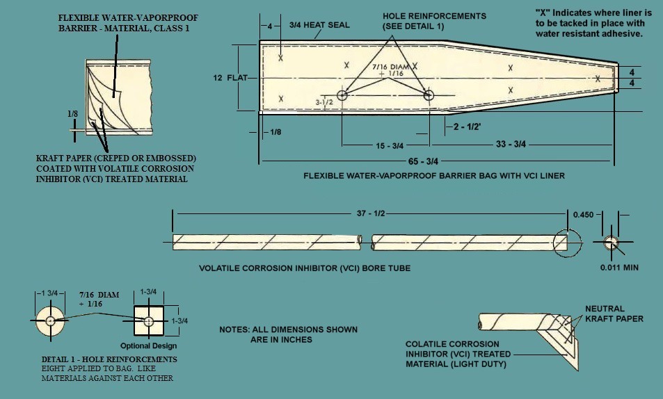
Figure 101. Volatile Corrosion Inhibitor (VCI) Bag and Bore Tube.
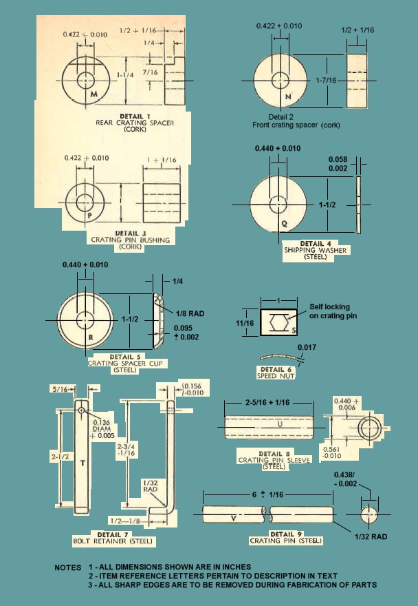
Figure 102. Crating pin assembly and bolt retainer details.
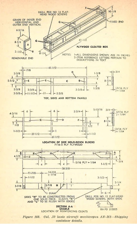
Figure 103. Basic aircraft machinegun AN-M3 - Shipping container details.
e. Packing.
(1) Construct a double-end, special style, cleated plywood box as prescribed in paragraph 128.
(2) Slide the packaged gun (muzzle encl first) into the open encl of the container. To avoid the possibility of ripping the shipping bag, do not allow bag to rub along inside of container.
Note. Place any instructions required for the gun in a waterproof envelope and pack inside the box.
(3) Secure removable end to container with eight No. 12 x 1 3/4 flat-head wood screws, two each at top, sides, and bottom (see figure 103).
Note. Heads of screws must not protrude and must not be hammered in.
(4) Apply three 3/s x 0.020 flat metal girth straps around both ends and middle cleats of the container. All straps must be drawn tight, so as to sink into the edges of the container. Apply strap seals and crimp. Staple all straps to the cleats of the box with cement-coated staples, spaced at intervals of approximately 6 inches.
Note. Strapping will be applied just prior to shipment.
f. Marking.
(1) Domestic.
(a) After weapon has been packed, the standard marking information required to mark containers for domestic shipment will be printed or stenciled directly on one surface, either the side or end of shipping container. This information will include standard nomenclature, stock number, or other identifying number, quantity and size, weight. (WT), package number (where required), domestic address label, caution labels and mar kings (where required), date packed (month and year), identification symbol of installation performing packaging, and method of preservation (including VCI code number and type of preservative used). In addition, if weapon has been packed for immediate use or limited storage, the container will be conspicuously marked PKD IMMED USE or PKG LTD STD, as applicable. The top cover will be stenciled with the following notation, in letters 1 inch high:
PRESERVATION-MIL-L-644: AND VCI
TO OPEN REMOVE SCREWS FROM END
REUSABLE CONTAINER-DO NOT DESTROY
Note. Whe11 set markings, packing list, and special and technical data markings are necessary, they will be used and applied in accordance with specific instructions from the officer in charge.
(b) Do not apply labels or mark containers unless contents have been actually inspected and processed.
(2) Oversea.
(a) When destined to ports of embarkation for oversea shipment, the container will be labeled or stenciled as prescribed for domestic shipment ((1) above) and, in addition, will include the cubage (CU), oversea address, and service color marking (see SR 746-30-5).
(b) Each container shipped to a port in less than a carload lot (LCL) or less than truckload lot (LTL) will also bear a domestic address; old addresses and irrelevant data will be effectively removed or obliterated prior to shipment. A label not exceeding 28 square inches (yellow corners not required on label) will be used for domestic addresses. Label will be securely attached to container and will be covered with water-resistant label adhesive. Stenciling of domestic addresses on containers is not permitted.
128. Construction of Shipping Container.
a. Shipping Box Data.
The data contained in table IX is for one cal. .50 basic aircraft machinegun AN-1VI3, packed in a double-end, special style, cleated plywood box (figure 103).
Note. Before constructing a quantity of these boxes, a tt·inl pack should be made and the dimensions of the container or blocking adjusted, if necessary,
TABLE IX. Shipping Box Data
| NUM | TITLE | SIZE |
| 1 | Length (in) | 61 1/2 |
| 2 | Width (in) | 8 1/4 |
| 3 | Height (in) | 10 1/8 |
| 4 | Area (sq ft) | 3.5 |
| 5 | Volume (sq ft) | 3.0 |
| 6 | Bearing pressure (lb per sq ft) | 27 |
| 7 | Ship tons (40 cu ft) | 0.07 |
| 8 | Shipping weight (gross lb approximate) | 97 |
| |
b. Bill of Materials. Table X lists the materials required to construct a double-end, special style, cleated plywood box (fig. 103) for one cal. .50 basic aircraft machinegun AN-M3. The box is to be constructed from group I or II lumber of standard thickness. All the plywood used for the container is constructed from groups I or II, type B, condition I lumber. The reference letters are those referred to in the text and figures 102 and 103.
TABLE X. Bill of materials.
Plywood container (Type B plywood, condition 1) (Figure 103)
| Actual Size (in.) | ||||||
| Num | Reference letters | Quantity required | Part name | Length | Width | Thickness |
| 1 | A | 2 | Ends (inner) * | 8 1/4 | 6 1/16 | 3/4 |
| 2 | B | 2 | Ends (outer) * | 6 5/16 | 8 1/4 | 3/4 |
| 3 | C | 4 | Top, sides, and bottom panels (3-plywood) | 61 1/2 | 8 1/4 | 3/16 |
| 4 | D | 8 | Edge cleats | 61 1/2 | 1 3/8 | 3/4 |
| 5 | E | 16 | Filler edge cleats | 5 1/2 | 2 3/8 | 3/4 |
| 6 | F | 2 | Side holddown blocks (5-ply plywood) | 5 13/16 | 2 3/4 | 7/16 |
| 7 | G | 4 | Side holddown blocks (5-ply plywood) | 6 | 4 3/16 | 7/16 |
| |
Cradle (pine, group I wood) (Figure 103)
| Actual Size (in.) | ||||||
| Num | Reference letters | Quantity required | Part name | Length | Width | Thickness |
| 1 | H | 2 | Sides b | 58 3/8 | 3 7/8 | 3/4 |
| 2 | J | 2 | Ends | 4 1/2 | 2 1/4 | 1 1/2 |
| 3 | K | 4 | Reinforcing cleats (5-ply plywood) | 4 | 3 7/8 | 8/16 |
| 4 | L | 2 | Reinforcing cleats (5-ply plywood) | 6 | 3 7/8 | 8/16 |
| |
Crating pin assemblies (Figure 102)
| Actual Size (in.) | ||||||
| Num | Reference letters | Quantity required | Part name | Length | Width | Thickness |
| 1 | M | 2 | Rear crating spacers (cork) (Detail 1) | ----- | 1 1/4 Diam | 1/2 |
| 2 | N | 2 | Front crating spacers (cork) (detail 2) | ------ | 1 7/16 Diam | 1/2 |
| 3 | P | 4 | Crating pin bushings (cork) (detail 3) | ------ | 1 Diam | 1 |
| 4 | Q | 4 | Shipping washers (steel) (detail 4) | ----- | 1 1/2 | .058 |
| 5 | R | 4 | Crating spacer cups (steel) (detail 5) | ----- | 1 1/2 Diam | 1/4 |
| 6 | S | 4 | Speed nuts (steel) (detail 6) | 1 | 11/16 | .017 |
| 7 | T | 1 | Bolt retainer (detail 7) | 1 | 11/16 | .017 |
| 8 | U | 1 | Crating pin sleeve (steel) (detail 8) | 2 5/16 | 0.561 diameter | ----- |
| 9 | V | 2 | Crating pins (steel) (detail 9) | 6 | 0.438 diameter | ----- |
| |
Bag and bore tube (Figure 101)
| Actual Size (in.) | ||||||
| Num | Reference letters | Quantity required | Part name | Length | Width | Thickness |
| 1 | ----- | 1 | Volatile corrosion inhibitor (VCI) bore tube. | 37 1/2 | 0.450 diameter | ----- |
| 2 | ----- | 1 | Flexible water - vaporproof barrier - material class i with kraft paper liner coated with volatile corrosioninhibitor (VCI) treated material. | 65 3/4 | 12 | ----- |
| |
Hardware
| Actual Size (in.) | ||||||
| Num | Reference letters | Quantity required | Part name | Length | Width | Thickness |
| 1 | ----- | 1 | Cotter pin, 1/4 x 1, type B, phosphate coated (for bolt retainer) | ----- | ----- | ----- |
| 2 | ----- | as required | Eightpenny cement - coated nails | ----- | ----- | ----- |
| 3 | ----- | As required | Flathead clout nails | 1 1/8 | ----- | ----- |
| 4 | ----- | 16 | Flathead steel wood screwa No. 12 x 1 3/4 (eight for cradle and eight for removable end). | ----- | ----- | ----- |
| 5 | ----- | As required | Fourpenny box nails. | ----- | ----- | ----- |
| 6 | ----- | As required | Staples. | ----- | ----- | ----- |
| 7 | ----- | 3 | Steel straps. | 40 | 3/8 | 0.020 |
| 8 | ----- | 3 | Steel strap seals | ----- | 3/8 | ----- |
| 9 | ----- | As required | Threepenny box nails | ----- | ----- | ----- |
| |
Cleaning and preserving materials.
| Actual Size (in.) | ||||||
| Num | Reference letters | Quantity required | Part name | Length | Width | Thickness |
| 1 | ----- | ----- | Bore brush (bristle) | ----- | ----- | ----- |
| 2 | ----- | ----- | Cloth or synthetic rubber gloves. | ----- | ----- | ----- |
| 3 | ----- | ----- | Dry-cleaning solvent. | ----- | ----- | ----- |
| 4 | ----- | ----- | Fingerprint remover. | ----- | ----- | ----- |
| 5 | ----- | ----- | Greaseproof barrier-material, Grade C | ----- | ----- | ----- |
| 6 | ----- | ----- | Preservative lubricating oil (special) (type P-9) | ----- | ----- | ----- |
| 7 | ----- | ----- | Quick-drying, lusterless enamel. | ----- | ----- | ----- |
| 8 | ----- | ----- | Rifle-bore cleaner. | ----- | ----- | ----- |
| 9 | ----- | ----- | Volatile mineral spirits | ----- | ----- | ----- |
| 10 | ----- | ----- | Wiping cloths (lint-free) | ----- | ----- | ----- |
| |
a. The double-end of box must be constructed with the grain of the Inner end horizontal and the outer end vertical. As an alternate method, ends may be constructed of one pieco having a thickness of 1~2 Inches.
b. Cradle sides are to be constructed from one solid piece.
c. Fastening Schedule.
Table XI lists the fastening schedule to be used when fabricating the box illustrated in figure 103. If the prescribed size of nails is not available, use the next smaller size and reduce the spacing of nails by one-quarter inch.
Table XI. Fastening schedule.
PLYWOOD CONTAINER (Figure 103)
| FASTEN | |||||
| Num | Part | To part | Nail size and type | Maximum spacing | Notes |
| 1 | Panels (C) | Cleats (D) and (E) | 1 1/2 in. clout | 3 | Stagger and clinch. |
| 2 | Holddown block (G) and (F) | Side panels (C) and cleats (D). | 4d box | 2 | Stagger abd clinch |
| 3 | Top and bottom | Sides | 8d cemented | 4 | Through side edge cleats (D) |
| 4 | Sides, top, and bottom. | Fixed end | 8d cemented | 2 1/2 | Stagger. |
| 5 | Sides, top, and bottom. | Removable end. | (See NOTES column) | ----- | Drill and fasten with No. 12 x 1 3/4 flathead wood screws; two per face. |
| |
CRADLE (Figure 103)
| FASTEN | |||||
| Num | Part | To part | Nail size and type | Maximum spacing | Notes |
| 1 | Reinforcing cleats (K) and (L) | Ends (H) | 3d box | 2 | Stagger and clinch. |
| 2 | Ends (J) | (See NOTES column) | ----- | Drill and fasten with No. 12 x 1 3/4 flathead wood screws; two screw per joint. | |
| |
d. Painting. The exterior surfaces ( except base) will be painted with one coat of quick-drying lusterless enamel. 129. Loadi~g and Blocking Instructions For general loading rules and methods and procedures for loading and blocking boxed items in boxcars, see TM 9-1005 and TB 9- 0SSG-A.
130. General.
a. Destruction of the cal. .50 basic aircraft machinegun AN-M3, when subject t capt1ure or abandonment in the combat zone, will be undertaken by the using arm only when, in the judgement of the unit commander concerned, such action is necessary in accordance with orders of, or policy established by, the Army commander. When these guns are in the posession of ordnance maintenance personnel or in storage destruction will be in accordance with FM 9-5 and applicable portions of the information in "b" through "d" below.
b. The information that follows is for guidance only. Certain of the procedures outlined require the use of explosives and incendiary grenades, which normally may not be authorized items for the airplane. The issue of these and related materials and the conditions under which destruction will be effected are command decisions in each case, according to the tactical situation. Of the several means of destruc· tion, those most generally applicable are~
| (1) | Mechanical | Requires axe, pick mattock, sledge, crowbar, or similar implement. |
| (2) | Burning | Requires gasoline, oil, incendiary grenades, or other flammables. |
| (3) | Demolition | Requires suitable explosives or ammunition. |
| (4) | Gunfire | Includes artillery, machine guns, rifles using rifle grenades, and launchers using antitank rockets. Under some circumstances hand grenades may be used. |
In general, destruction of the essential parts by mechanical means will usually be sufficient to render the nrnchinegun useless. However, selection of the particular method of destruction requires imagination and resourcefulness in the utilization of the facilities at hand under the existing conditions. Time is usually critical.
c. If destruction to prevent enemy use is resorted to, the machinegun must be so badly damaged that it cannot be restored to a usuable condition in the combat zone either by repair or cannibalization. Adequate destruction requires that all parts essential to the operation of the machinegun, including essential spare parts, be destroyed or damaged beyond repair. However, when lack of time and personnel prevents destruction of all parts, priority is given to the destruction of those parts most difficult to replace. Equally important, the same essential part must be destroyed on all like materiel, so that the enemy cannot construct one complete unit from several damaged ones.
d. If destruction is directed, due consideration should be given to the factors in (1) and (2) below.
(1) Selection of a point of destruction that will cause greatest obstruction to enemy movement and also prevent hazard to friendly troops from fragments or richocheting projectiles that may occur incidental to the destruction.
(2) Observance of appropriate safety precautions.
131. Destruction of the Cal. .50 Basic Aircraft Machinegun AN-M3
a. General.
If time, personnel, and materials are available, the destruction of the armament should be accomplished in conjunction with the destruction of the airplane by incendiary means. However, if it is inadvisable to destroy the airplane by fire or if the armament is to be destroyed separately from the airplane, the armament should be removed from its mounting and be destroyed by one of the methods outlined in "b" through "d" below.
b. Method No.1- by Smashing. Using an axe, pick mattock, sledge, or other heavy implement, smash the feed mechanism, retracting slide stud assembly, backplate assembly, cover assembly, receiver, barrel jacket, and barrel. Elapsed time: about 2 minutes.
c. Method No. 2 - by Demolition.
(1) Place the machinegun on the ground.
(2) Prepare a 1-pound charge of EXPLOSIVE, TNT (using a 1-lb. block or equivalent together with necessary detonating cord) and place the charge on the receiver.
(3) For priming, either a nonelectric blasting cap crimped to at least 5 feet of safety fuse ( safety fuse burns at the rate of 1 :ft. in 30 to 45 sec. ; test before using) or an electric blasting cap and firing wire may be used. Safety fuse, which contains black powder, and blasting caps must be protected from moisture at all times. The safety fuse may be ignited by a fuse lighter or a match; the elf~ctric blasting cap rcqnires a blasting machine or equivalent source of electricity. Caution: Keep the blasting caps, detonating cord, and safety fuse separated from the charges until required for use. Note. For the successful execution of methods of destruction involving the use of demolition materials, all personnel concerned will be thoroughly familiar with the pertinent provisions of FM 5-25. Training and careful planning are essential.
(4) Detonate the charge. If primed with nonelectric blasting cap and safety fuse, ignite and take cover. If primed with electric blasting cap, taJrn cover before firing the charge. The danger zone is approximately 200 yards. Elapsed time: about 2 minutes.
d. Method No. 3-by Burning (Incendiary Grenades).
(1) Place the machinegun on the ground.
(2) Raise the cover assembly.
(3) Place nn incendiary grenade on the bolt assembly.
(4) Fire grenade. Elapsed time: about 1 minute.
1. Publication Indexes
Special regulations in the 310-20-series, DA Pamphlet 310- series, DA Pam 108-1, and FM 21-8 should be consulted frequently for latest changes or revisions of refere11ces given in this appendix and for new publications relating to materiel covered in this manual.
2. Supply Manuals
The following manuals of the Department of the Army supply manual pertain to this materiel:
a. Ammunition.
| Ammunition, rifle, carbine, and automatic gun. | ORD 3 SNL T-1 | Shipping and packing containers and materials, including such items as bandoleers, belts, clips, links and ends for small arms ammunition. | ORD 3 SNL T-5 |
b. Destruction to Prevent Enemy Use.
| Land mines and components; Demolition Explosives and Related Items; and Ammunition for Simulated Artillery, Booby Trap, and Land Mine Fire. | ORD 3 SNL R-7 |
c. General.
| Introduction | ORD I |
d. Maintenance and Repair.
| Cleaners, Preservatives, Lubricants, Recoil Fluids, Special oils, and related maintenance materials. | ORD 3 SNL K-1 |
| Shop set, small arms, field maintenance. | ORD 6 SNT, J8, Sec 6 |
| Special tool sets for small arms and automatic weapons (SNL Groups A and B). | ORD (*) SNL J-12 |
| Tool set, armorers (MOS 0511) | ORD 6 SNL J-10, Sec 1 |
| Tool set, small arms repairman (Ordnance) (MOS 0903) | ORD 6 SNL J-10, Sec 2 |
| Truck 2 1/2 ton, 6 x 6, small arms repair, M7A1 and M7A2. | ORD 7 SNL G-138, Vol 1 |
e. Weapon.
| Gun, machine, Cal. .50, AN-M3, Aircraft basic. | ORD (*) SNL A-67 |
* See DA PAM 310-29, Index of supply manuals - Ordnance Corps, for published types of manuals of the ordnance section of the department of the Army supply manual.
3. Forms
The following forms pertain to- this materiel :
AF Form 54, Unsatisfactory Report.
AF Form 185, Maintenance and Performance Record.
DA Form 452-1, Placard-Documents Covering Shipment are on OTHER SIDE of Car.
DA Form 452-2, Placard-Documents Covering Shipment are on THIS SIDE of Car.
DA Form 468, Unsatisfactory Equipment Report.
DA Label 16, Method II Pack Lnbel (small size).
DA Label 17, Method II Pack Label (large size).
DD Form 6, Report of Diunaged 01· Improper Shipment.
4. Other publications
The following explanatory publications contain information pertinent to this mnteriel and associated equipment: