Donate
Claymore Mine Appendix.
APPENDIX I - M18 ANTIPERSONNEL MINE.
1. General
The M18 antipersonnel mine is an earlier model of the M18Al antipersonnel mine, which is described in chapters 1 and 2. The difference between the two models may be seen by com paring figure 20 with figures 1 and 7. The M18 and the M18Al are similar in use and functioning. The M18 antipersonnel mine is now limited standard.
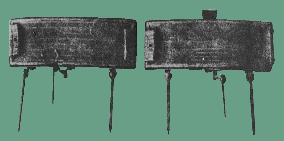
Figure 20. The M18 antipersonnel mine without sight on left. With sight on right.
2. Description.
a. General. The M18 antipersonnel mine comes in two versions-with or without a peep sight; otherwise, both versions are identical (fig. 20). The mine is a curved, rectangular, plastic case and contains a layer of composition C3 explosive. It has a fragmentation face of rectangular steel fragments. The front face containing the steel fragments is designed to produce a fan-shaped spray which can be aimed at a prescribed target area. The arrow marked on top of each mine indicates the direction of aiming. The mine has three folding-type legs and cloth tabs on each side of the mine. The legs of the mine are used to emplace it above the ground; the cloth tabs are used to tie or nail the mine to trees or posts.
There is a horizontal cap well on each side of the mine. To reduce detection, the mine is covered in a camouflage pattern of green and brown fleck.
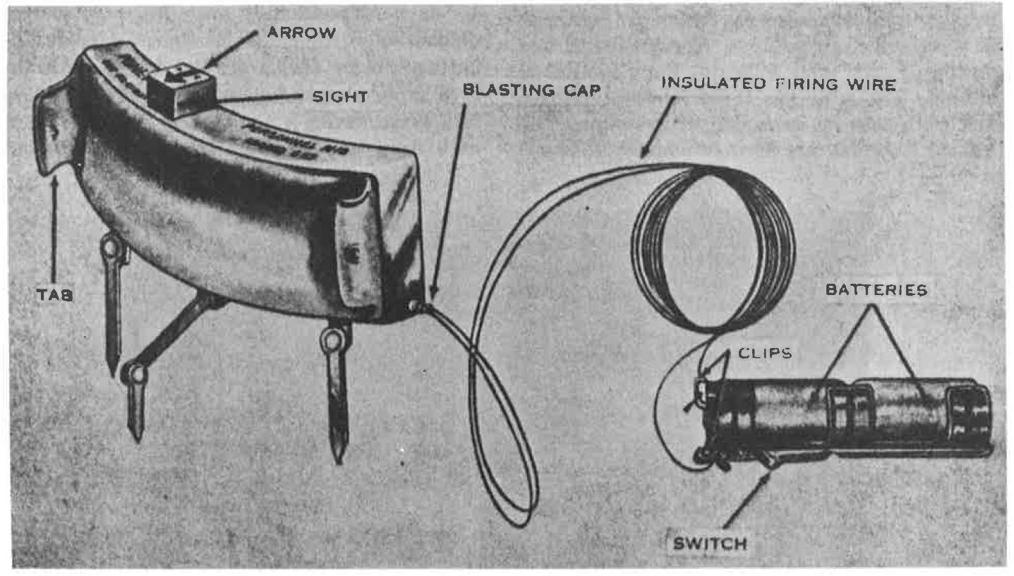
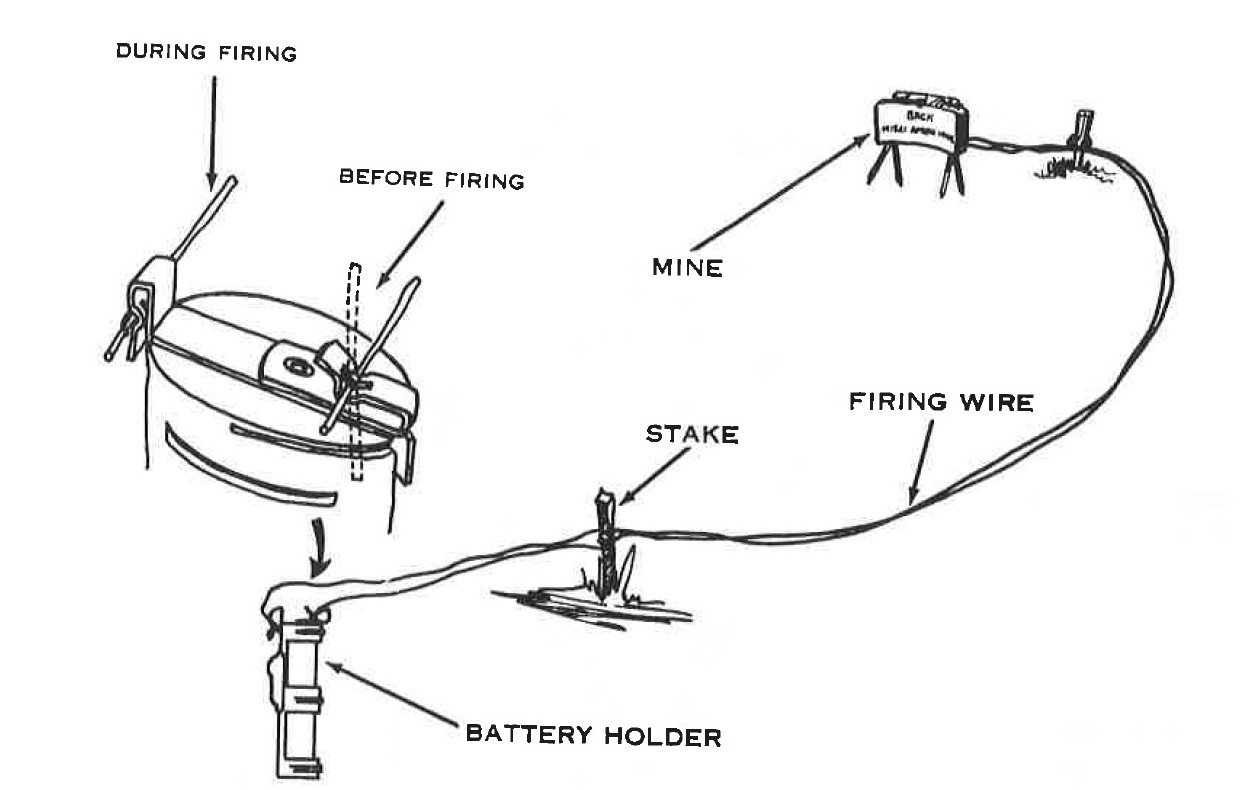
Figure 21. The M18 antipersonnel mine with electric blasting cap and lead wires, batteries, and battery holder.
b. Detailed Description.
(1) Weight : 2 1/2 pounds.
(2) Detonator : Electric blasting cap.
(3) Explosive : 3/4 pound C-3 explosive.
(4) Firing : 50 feet (2-strand). wire.
(5) Firing device: Plastic frame with metal flashlight-type electric switch. Frame holds two 1.5-volt BA-30 dry batteries.
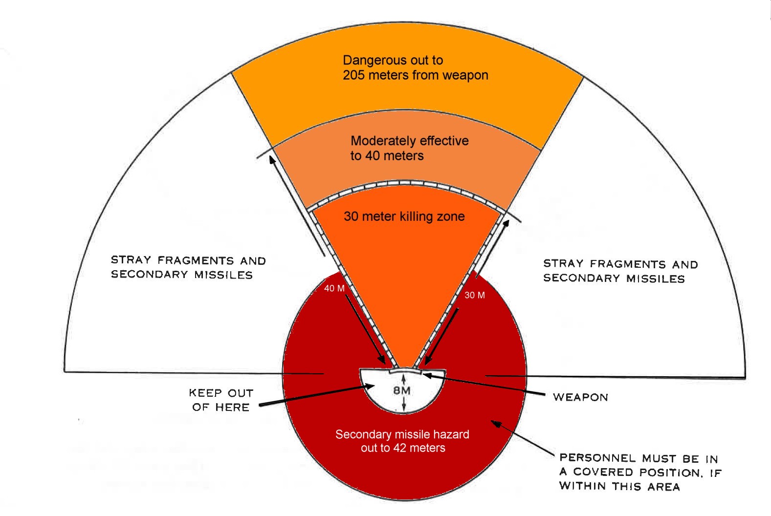
b. Danger Area (fig. 22).
(1) Danger from fragments. The danger area consists of an 80° fan with a distance of 205 meters centered in the direction of aim of the mine.
(2) Danger from back blast and secondary missiles to the rear and sides of the mine.
(a) Distance of O to 8 meters from the mine. Friendly troops are prohibited in this area.
(b) Distance of 8 to 16 meters from the mine. Friendly troops must lie prone or be in foxholes.
Distance of 16 to 50 meters from the mine. If all potential secondary missiles have been removed within a 1-meter radius to the rear and sides of the mine, friendly troops need only shut their eyes when the mine is detonated.
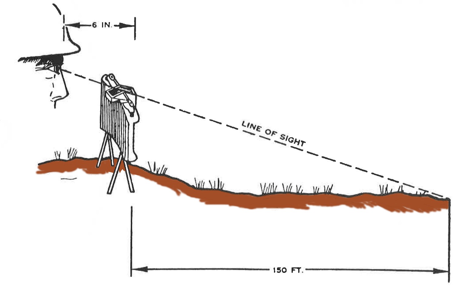
(4) For installation on a tree or post, the mine legs should remain folded. Utilizing the holes in the cloth tabs of the mine, secure it to the tree or post by tying or nailing. For either method of installation, the arrow on the top of the mine must point at the center of the fragmentation pattern.
(5) After placement of the mine, completely unwind the 50 feet of lead wires and run them to the firing position. Camouflage the mine and wire. The lead wires may be laid on top of the ground; however , if time permits they should be buried underground. This will reduce the possibility of artillery fragments dislodging the mine and cutting the wires. Lead wires of Ml8 mines that are tactically employed must be twisted together and taped at two or more equidistant places. Leads must also be shunted.
This can be accomplished by attaching both leads to the clip on the battery holder nearest the switch. The shunt must then be removed by detaching one of the leads and attaching it to the other clip on the battery holder before installing batteries and firing.
b. Preparation and firing.
(1) M18 mine with M68 carrying kit.
(2) M18 mine with M69 carrying kit and other firing devices.
(a) The M18 mine packed in the M69 carrying kit is designed for armor use. The mine is fired by connecting the lead wires to the battery of a tank or other types of vehicles.
(b) This mine may also be fired using pull-type firing devices, nonelectric blasting caps, and a sufficient length of detonating cord to bridge the distance between the mine and the firing devices. (See para 13, chapter 3 for a detailed description.)
c. Disarming.
(1) If dry cell batteries and battery holder (s) are utilized, insure that the switches are in the OFF position, and remove lead wires from the clips of the holder.
(2) Short the lead wires by twisting the bare ends together.
(3) Carefully remove the blasting cap from the mine.
(4) Rewind lead wires and return the blasting cap and wire to the cardboard tube.
(5) Remove the mine from its installed position, fold the legs (if required), and place the mine into its original packing.
APPENDIX II - SAFETY.
X. General This appendix covers the safety precautions to be observed when firing the M18Al and M18 antipersonnel mines for training purposes. These safety precautions will assist the instructor in conducting CLAYMORE training. They are intended as a guide only and must be used in conjunction with appropriate safety measures prescribed in Army and/or local installation regulations.
2. Safety Precautions
a. Before firing, the officer in charge (OIC) will check all mines to insure that-
(1) Mines are installed correctly.
(2) The fragmentation face of the mine is pointed into the impact area and away from friendly troops.
b. CLAYMORES will be installed only on command of the OIC.
c. All mines will be kept under guard until the OIC directs their issue.
d. Once a mine has been emplaced for firing it will not be disarmed, except by order of the OIC.
e. The firing wire will not be connected to the firing device until ordered by the OIC.
f. When more than one mine is to be fired, the OIC will insure that a previous firing has not dislodged other mines in the impact area.
g. No one will enter the impact area without the approval of the OIC.
h. After firing, the impact area will be in spected to insure that all mines have detonated.
3. Operational Safety Factors
a. An individual installing a mine will carry the firing device on his person.
b. Mines must be installed in a manner that will prevent them from becoming disoriented.
c. Blasting caps will not be inserted into the detonator wells until the mine has been emplaced in its firing position and aimed.
d. The safety bail on the firing device must be in the SAFE position after the completion of the firing circuit test.
e. The shunt will not be removed from the firing wire of the M18 until the operator is ready to connect it to the firing device. Before installing batteries and firing, leads can be shunted by attaching both leads to the clip on the battery holder.
f. Firing wire leads of the M18 mines that are tactically employed must be twisted together and taped at two or more equidistant places.
4. Misfires
a. Electrical Firing System. A misfire of an electrically employed M18Al must be investigated immediately. If the mine is dual-primed with both electric and nonelectric caps, it will then be necessary to wait 30 minutes before investigating the cause of the misfire. When handling electrical misfires, the following steps will be taken: (1) Shout MISFIRE ( non-tactical). (2) Check the firing device connection to the firing wire connector; make two attempts to fire the mine. (3) Using the M40 test set, check the continuity of the electric firing circuit.
Note. Only one man at a time will investigate the cause of an electric misfire.
b. Nonelectrical Firing System. If the non electric blasting cap initiator attached to the detonating cord fails to function, delay ` investigation for at least 30 minutes. Then cut the detonating cord between the firing device and the mine and fasten a new firing device to the detonating cord. If the detonating cord leading to the mine detonates, but the mine fails to detonate, delay investigation until it is certain that the mine is not burning. If the mine is not damaged, insert a new blasting cap with detonating cord. In training, if the mine appears to be damaged, it should be treated as a dud and destroyed as instructed in TM 9-1800-206.
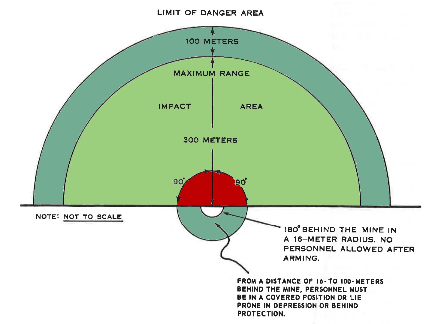
NOTE: When the mine is tied to a tree or fired in some other area where the secondary missile hazard cannot be removed, friendly troops in a 16 to 50 meter radius behind the mine must be in a covered position.
APPENDIX III - TRAINING AIDES.
1. General
Training aids should be used to the maxi mum during phase I and phase II training. A model, picture, or chart can be used to explain how the mine functions or is installed. Effective training aids improve instruction and increase understanding.
2. Training Aids
a. Training film 7-3180, "Technique of Employment, M18 and M18Al Antipersonnel Weapons (CLAYMORE)," 27 minutes.
b. Graphic training aid (GTA) 7-1-1, "Ml8Al Antipersonnel Mine, (CLAYMORE)" illustrates the mine and its methods of employment.
c. When the training film and GTA are not available, figures 3, 10, 11, and 24 illustrate the type of training aids that can be used to conduct phase I training. These training aids should not limit the instructor's imagination or replace any other aids which may be available or listed in training aids catalogs. Wherever possible, local training aids centers should be utilized to obtain desired training aids and devices. These centers will loan and/or fabricate the required aids and devices.
