Donate
The U. S. Claymore Mine.
CHAPTER 1 - INTRODUCTION.
1. Purpose and Scope.
a. This manual provides guidance for commanders and instructors presenting instruction and training on the functioning, installation, and employment of the antipersonnel mine, CLAYMORE.
b. This manual describes the M18Al antipersonnel mine, CLAYMORE, its functioning, and installation. It provides a basis for con ducting training utilizing the electric firing system issued with the mine. It also gives guidance for tactical employment and safety requirements. An earlier model of the CLAYMORE antipersonnel mine, the M18, is covered in appendix II.
c. The material contained herein is applicable without modification to both nuclear and nonnuclear warfare.
d. Users of this manual are encouraged to submit recommended changes or comments to improve the publication. Comments should be keyed to the specific page, paragraph, and line of the text in which the change is recommended. Reasons should be provided for each comment to insure understanding and complete evaluation. Comments should be for warded direct to the Commandant, United States Army Infantry School, Fort Benning, Ga. 31905.
2. Roles of the antipersonnel mine, CLAYMORE.
The number of ways in which the CLAY MORE may be employed is limited only by the imagination of the user. The CLAYMORE is used primarily as a defensive weapon, but has its application in the offensive role. It must be emphasized that when the CLAY MORE is referred to as a weapon, this implies that it is employed in the controlled role. In the uncontrolled role, the CLAYMORE is considered a mine or booby trap (FM 20-32).
Figure 1. The M18A1 antipersonnel mine (CLAYMORE).
Figure 3. Claymore mine instruction sheet.
3. General.
The M18Al antipersonnel mine was standardized in 1960, and replaced the M18 anti personnel mine (app. II). Both mines are similar in appearance and functioning. The M18Al (fig. 1) is a directional, fixed-fragmentation mine. When employed in the controlled role, it is treated as a one-shot weapon. It is primarily designed for use against massed infantry attacks; however, its fragments are also effective against light vehicles.• The M18Al mine is equipped with a fixer plastic slit-type sight, adjustable legs, and two detonator in the M7 bandoleer (fig. 2). The instruction sheet for the M18Al is shown in figure 3.
The mine and all its accessories are carried wells.
4. Casualty effects.
When detonated, the M18Al mine will de liver spherical steel fragments over a 60° fan shaped pattern that is 2 meters high and 50 meters wide at a range of 50 meters (fig. 4). These fragments are moderately effective up to a range of 100 meters and can travel up to 250 meters forward of the mine. The optimum effective range (the range at which the most desirable balance is achieved between lethality and area coverage) is 50 meters.
5. Danger areas.
a. Danger From Fragments (fig. 4). The danger area consists of a 180° fan with a radius. of 250 meters centered in the direction of aim.
b. Danger Area of Back blast and Secondary Missiles (figs. 4 and 24). Within an area of 16 meters to the rear and sides of the mine, back blast can cause injury by concussion (ruptured eardrums) and create a secondary missile hazard.
(1) Friendly troops are prohibited to the rear and sides of the mine within a radius of 16 meters.
(2) The minimum safe operating distance from the mine is 16 meters. At this distance, and regardless of how the mine is employed, the operator should be in a foxhole, behind cover, or lying prone in a depression. The operator and all friendly troops within 100 meters of the mine must take cover to prevent being injured by flying secondary objects such as sticks, stones, and pebbles.
Figure 2. The M18A1 antipersonnel mine and accessories packed in the M7 bandoleer. ` |
Figure 4. Danger radius and effects of the M18A1. |
CHAPTER 2 - MECHANICAL TRAINING.
6. General.
This section describes and illustrates the M18Al antipersonnel mine and the electric and nonelectric firing systems that can be used to detonate the mine.
1. Detailed description.
a. Mine.
(1) Nomenclature Mine, antipersonnel, M18Al.
(2) Common name: CLAYMORE.
(3) Type: Antipersonnel.
(4) Weight : 3½ pounds.
(5) Dimensions: 8½ incheslong; 13/a inches wide; 3¼ inches high (legs folded) ; 68/4 inches high (legs unfolded).
(6) Firing unit construction : The outer surface of the mine is a curved, rectangular, olive-drab, molded case of fiberglass-filled polystyrene (plastic) . In the front portion of the case is a fragmentation face containing steel spheres embedded in a plastic matrix. The back portion of the case behind the matrix contains a layer of explosive.
(7) Explosive: 1 1/2 pounds of composition C4.
(8) Detonator wells: Two detonator wells are located on the top of the mine which allows for single or dual priming. These wells are sealed by the plug ends of the shipping plug priming-adapters which prevent entry of foreign materials into the detonator wells. The slotted end of the shipping plug priming-adapter is used to hold an electric blasting cap in place when the mine is armed. The shipping plug priming-adapter is merely reversed when the mine is to be armed.
(9) Peepsight and arrows. The molded slit-type peepsight and arrows (fig.10) located on top of the mine are used to aim the mine.
(10) Legs. Two pairs of scissors-type folding legs located on the bottom of the mine enable it to be emplaced on the ground. The mine can also be tied to posts, trees, etc.
b. Accessories.
(1) M57 firing device.
(a) One M57 electrical firing device is issued with each M18Al. This de vice is a hand-held pulse generator. A squeeze of the handle produces a double (one positive, one negative) 3-volt electric pulse of sufficient energy to fire the electric blasting cap through the 100 feet of firing wire which is issued with the mine. The M57 device is 4 inches long, approximately 1½ inches wide, 3¼ inches high, and weighs three-fourths of a pound. On one end of the firing device a rubber connecting plug with a dust cover.
|
The M57 firing device is shown in fogure 5.
The safety bail on the M67 electrical firing device (fig. 6) has two positions. In the upper SAFE position, it acts as a block between the firing handle and the pulse genera tor. In the lower FIRE position, it is clear of the firing handle and allows the pulse generator to be activated. The M18Al antipersonnel mine with the M57 firing device connected is shown in figure 7. (2) M4 electric blasting cap. The M4 electric blasting cap (fig. 7) consists of an M6 electric blasting cap attached to 100 feet of firing wire. Attached to the firing wire connection is a combination shorting plug and dust cover. The shorting plug prevents accidental functioning of the blasting cap by static electricity; the dust cover pre vents dirt and moisture from |
Figure 6. The M57 firing device safety bail. |
Figure 5. The M57 firing device. |
entering the connector. The firing wire is wrapped around a flat paper and then rolled to form a package 6 inches long, 4• inches wide, and 2
inches high. A piece of insulating tape is used to hold the package together.
(8) M40 test set. The M40 test set (figs. 17 and 18) is an instrument used for checking the continuity of the initiating- circuit of the mine. (For further details on the M40 test set, see para 16.) Note. Only one of the six bandoleers in each packing box contains a test set. The bandoleer containing the test set is marked by an identification tag on the carrying strap (fig. 2). |
c. M7 Bandoleer. The M7 bandoleer (fig. 2) is constructed of water resistant canvas (olive drab color) and has snap fasteners which secure the flap. The bandoleer has two pockets; one pocket contains the mine and the other contains a firing device, a test set, and an electric blasting cap assembly. A 2-inch wide web strap, which is used as a shoulder carrying strap, is sewn to the bag. An instruction sheet is sewn to the inside flap (fig. 3).
Figure 7. The M18A1 antipersonnel mine witht he M-57 firing device connected.
8. Fire discipline.
Since the M18Al mine can be fired only once. fire discipline is of paramount importance. The mine should not be used against single personnel targets; rather, it should be used for its in tended purpose-massed personnel. When lead elements of an enemy formation approach with in 20 to 30 meters of the mine, it should be detonated. If practicable, and to insure fire discipline, actual authority and responsibility for target selection and timely detonation should rest with squad leaders or their superiors.
9. Controlled frontage coverage.
a. For effective coverage of the entire front of a position, mines can be placed in a line no closer than 5 meters and no farther apart than 45 meters. Preferred lateral and rearward separation distance is 25 meters (fig. 8).
b. If mines are placed in depth (from front to rear), the minimum rearward separation distance is 5 meters, provided secondary missiles are removed. This distance is sufficient to prevent possible disturbance or damage to the rearward mines.
10. Method of fire.
The M18Al mine can be employed in either the controlled or uncontrolled role.
a. Controlled Role. The mine is detonated by the operator as the forward edge of the enemy approaches a point within the killing zone (20 to 30 meters) where maximum casual ties can be inflicted. Controlled detonation may be accomplished by use of either an electrical or nonelectrical firing system (fig. 9). When mines are employed in the controlled role, they are treated the same as individual weapons and are reported for inclusion in the unit fire plan. They are not reported as mines however, the emplacing unit must insure that the mines are either removed, detonated, or turned over to a relieving unit.
b. Uncontrolled Role. Uncontrolled firing is accomplished when the mine is installed in such a manner as to cause an unsuspecting enemy to detonate the mine. Mines employed in this manner must be reported and recorded as land mines.
11. Functioning.
a. Electrical Firing. When the M18Al is armed, actuating the M57 firing device handle (fig. 5) with the safety bail in the FIRE position provides sufficient electrical energy to detonate the M6 electric blasting cap. The detonation of the blasting cap, in turn, sets off the high explosive charge (composition C4). Detonation of the high explosive charge causes fragmentation of the plastic matrix and pro jects spherical steel fragments outward in a fan-shaped pattern (fig. 4). This mine is sufficiently waterproof to function satisfactorily after having been submerged in salt or fresh water for 2 hours.
b. Nonelectrical Firing. The M18Al mine is deliberately detonated by the operator pulling or cutting a tripwire attached to a nonelectrical firing device (fig. 9). A nonelectric blasting cap attached to the firing device and crimped to a length of detonating cord sets off the detonating cord. At the other end of the detonating cord.
A second crimped nonelectric blasting cap, which is inserted in one of the detonator wells detonates the mine.
12. installation of electrical firing.
a. Laying and Aiming.
(1) Remove the mine and accessories (fig.2) from the bandoleer. Read the instruction sheet (fig. 3) attached to the flap of the bandoleer before proceeding with the installation of the mine.
(2) The M57 firing device must be in the possession of the individual installing the mine. This prevents accidental firing by a second individual.
(3) Turn the legs downward and spread them about 45° apart. Twist both pairs of legs so that one leg protrudes ahead and one behind the mine, and position the mine so that the surface marked FRONT TOWARD ENEMY.
Figure 8. Diagram of lateral separation pattern of Claymores.
and the arrows on top of the case point in the direction of the enemy or the desired area of fire. On snow or extremely soft ground (mud), the bandoleer may be spread beneath the mine for support. To prevent the mine from tipping in windy areas, or when the legs cannot be pressed into the ground, carefully spread the legs to the maximum width (approximately 180°) so that the legs will be to the front and rear of the mine. A top view of the M18Al antipersonnel mine is shown in figure 10.
(4) Select an aiming point (tree, bush, etc.) that is approximately 150 feet from the mine and which projects approximately 8 feet above the ground (fig. 11) . This approximates 2½ meters at a distance of 50 meters. Position the eye approximately 6 inches (15 cm.) away from the mine and aim the mine by sighting through the peepsight. The groove of the sight should be in line with the aiming point. The aiming point should be in the center of the desired area of coverage, and the bottom edge of the peepsight should be parallel to the ground that is to be covered with the fragment spray.
Figure 10. Top view of the M18A1 antipersonnel mine. |
b. Arming and Electrical Firing.
(1) Unscrew either the right or left shipping plug priming-adapter, and reverse it to allow the firing wire to be placed into the slot provided in the priming-adapter portion (fig. 12). Remove the insulation tape and un roll the paper form from the firing wire. Make sure that the firing wire is uncoiled without tangling or kinking. Retain the paper fo1,n and the tape for possible future use. Hold the blasting cap while unwinding approximately 3 meters of the firing wire. |
Make certain that the combination shorting plug and dust cover are assembled to the connector of the firing wire before placing the blasting cap into the detonator well. Wrap the firing wire around a stake located approximately 1 meter from the mine to prevent the mine from becoming misaligned if the firing wire is disturbed.
|
(2) A firing circuit test (para 15) should be conducted before the blasting cap is placed into the detonator well. This test checks the continuity
of the firing circuit.
(3) Slide the slotted end of the shipping plug priming-adapter on the firing wires of the blasting cap between the crimped connections and the blasting cap. Pull the excess wire through the slotted end of the shipping plug priming-adapter until the top of the blasting cap is firmly seated in the bottom portion of the shipping plug priming adapter. Screw the shipping plug priming-adapter and the blasting cap into the detonator well. Warning: Make certain that the face of the mine marked "front toward enemy" and the arrows on top of the mine point in the direction of the enemy. |
Figure 11. Aiming the M18A1 antipersonnel mine. |
(4) Recheck the aim of the mine. Camouflage the mine and unwind the remaining firing wire to the firing position. If possible, bury the firing wire to protect it from artillery fire and detection. The operator should be in a foxhole, or in a covered position at least 16 meters behind or to the side of the emplaced mine. If possible, perform the tests in para graph 15 before arming the M18Al. If the area is subjected to mortar or artillery bombardment, retest the circuit.
(5) Remove the dust cover from the connector on the firing device; also, re move the combination shorting plug and dust cover from the end of the firing wire. Plug in the two connectors. Before connecting the firing wire to the M57 firing device (fig. 5),
Figure 9. Diagram of the M18A1 antipersonnel mine installed for controlled nonelectrical and electrical detonation. |
the safety bail must be in the SAFE position. Before attaching the firing device, insure that personnel are un der cover at least 250 meters away
from the front and sides of the mine and at least 100 meters to the rear of the mine. The firing device should not be connected to the firing
wire until the actual time of firing.
(6) After testing (para 15), the mine is ready for firing. To fire the mine, position the firing device bail in the FIRE position. (7) Fire with a firm, quick squeeze of the firing device handle. |
13. Installation of non electrical firing.
A nonelectric firing system utilizing a ring main is shown in figure 13. Instructions for laying, aiming, and arming the mine using two nonelectric M7 blasting caps, a piece of detonating cord approximately 25 feet long, a pull wire, and a pull-type or pull release-type firing device, such as the Ml or the M3 is discussed in a and b below. Instructions for laying, aiming, and arming the mine using a dual firing system and a ring main is discussed in c below. To arm the mine by the methods described below, a thorough knowledge of ex plosives and demolition materials and the use and installation of land mines and booby traps is required. Material on these subjects and techniques is contained in FM 3-5, FM 5-25, FM 5-31, FM 20-32, FM 31-10, TM 9-1375-200 and TM 9-1345-200.
a. Pull Wire Initiation of the Mine (con trolled).
(1) Laying and aiming the mine are performed in the same manner as for electrical firing. For details on laying and aiming, see paragraph 12a.
|
(2) Crimp a nonelectric blasting cap to a firing device. With the nonelectric blasting cap attached, fasten the firing device to the detonating
cord with tape. Using tape, wire, twine or cord, fasten the firing device securely to a firmly emplaced stake (fig. 13). Insert the detonating
cord into a second nonelectric blasting cap and crimp the cap to the detonating cord. Carefully insert the cap into the detonator well.
Secure the cap in the detonator well by carefully taping or tying the detonating cord to the mine. A method of taping detonating cord to a
nonelectric blasting cap is shown in Figure 14.
(3) Attach a pull wire securely to the pull ring of the firing device. The pull wire should be sufficiently long to allow actuation of the firing device from a protected position at least 16 meters to the rear of the mine. Care must be taken during emplacement to secure the firing device so that the mine will not be dislodged by a pull of the detonating cord of the trip- wire. |
Figure 12. Arming and testing the M18A1 antipersonnel mine. |
b. Tripwire initiation of the mine (uncontrolled).
(1) Laying and aiming the mine are performed in the same manner as for electrical firing. For details on laying and aiming, see paragraph 12a.
(2) The preliminary steps used to arm the mine are the same as those de scribed in a ( 1) through (3) above.
(3) The tripwire and the firing device, which are stretched across a trail or other avenues of approach, must be securely attached to two stakes firmly emplaced in the ground at a distance of 20 to 30 meters forward of the mine (fig. 15).
Figure 13. Nonelectric firing system. |
c. Nonelectric Method Using Dual Firing or Ring Main.
(1) Dual firing. (a) Obtain two 10-meter lengths of detonating cord, four M7 nonelectric blasting caps, and two pull-type firing devices. Details for using dual firing or ring main systems are contained in FM 5-26. (b) Remove both shipping plug prim ing-adapters from the mine. (c) Crimp an M7 nonelectric blasting cap to the end of each piece of detonating cord. Insert the capsinto the detonator wells, and carefully tape or tie the detonating cord to the mine. While moving back to a safe firing position, unwind the detonating cord. (d) Emplace the mine and the detonating cord as described in a(l) through (3) above. (e) Attach a pull-type firing device and a tripwire (or pull wire) to the free end of each piece of detonating cord (figure 18). Use the procedures described in a or b above. |
(2) Ring Main.
(a) Follow the instructions in (1) (a) through (d) above,
(b) Make a ring main as described in FM 6-26 (fig. 18).
|
(c) When mines are emplaced one be hind the other, the one nearest the enemy is generally fired first. Mines emplaced laterally may be fired in any
order or simultaneously.
(d) The mine and the danger area around the mine must be visible from the firing position so that friendly personnel in the vicinity of the mine may be seen. |
Figure 14. Method of taping MS firing device to detonating cord. |
14. Camouflage.
a. Although the M18Al is painted olive-drab to facilitate camouflaging, it is necessary to blend the m!.ne into its surroundings to prevent its detection.
b. Only lightweight foliage, such as leaves and grass should be used to avoid increasing the secondary missile hazard to the rear of the mine.
c. Both the front and rear of the mine should be camouflaged with foliage. The firing wire should also be camouflaged or buried underground. If used, detonating cord should not be buried; however, it may be covered with light foliage. For the principles and methods of camouflage, see FM 5-20.
15. Testing.
a. M40 Test Set. One M40 test set is provided with each case of six M18Al's. The test set is an instrument used for checking the continuity of the electrical firing circuit. A shipping tag on the carrying strap marks the bandoleer which contains the test set. The test Set is 2 inches long, 1½ inches high, and weighs 8 ounces. A small window is located on top of the test set and is used for observing the flashes of the indicating lamp (figures 17 and 18) . The M18Al antipersonnel mine set up for circuit testing is shown in figure 16.
Figure 15. Diagram of the M18A1 antipersonnel mine installed for uncontrolled firing.
b. Detailed Circuit Testing Procedure. The firing circuit test should be conducted before the blasting cap is placed into the detonator well. This precaution will prevent the destruction of the mine if the testing set mal functions and detonates the electric blasting cap. If the blasting cap is detonated during testing, it can be replaced by a standard electric blasting cap attached to the remaining firing wire. Before and after completion of the firing device and blasting cap continuity tests, ascertain that the firing device safety bail is in the SAFE position.
(1) Testing the M57 firing device and the M 40 test set.
(a) Remove the dust cover from the connector of the firing device and from the female connector of the test set. Plug the test set into the firing device (fig. 5). Leave the combination shorting plug and dust cover assembly on the other end of the test set. Position the firing device bail to the FIRE position and actuate the handle of the firing device with a firm, quick squeeze and observe the flashing of the lamp through the window of the test set. The window of the test set should be held near the eye when checking the firing device and blasting cap circuitry. This minimizes the risk of enemy observation in the dark and enables the operator to see the lamp flashing, even in bright sunlight.
|
(b) Flashing of the lamp indicates that the firing device is functioning properly. If the lamp does not flash ( on and off), it could be caused
by corrosion on the electric connectors of the test set. The firer can overcome this by connecting and disconnecting the shorting plug dust cover
on the M40 test set. If the test set indicates that several firing devices are faulty, retest with an other set since the first one may be
defective. Side and top views of the M40 test set are shown in figures 17 and 18.
(2) Testing the blasting cap. (a) After determining that the firing device and test set are operative, remove the shorting plug dust cover from the connector of the firing wire and from the end of the test set. Plug the connector of the firing wire into the test set. Position the M57 firing device bail to the FIRE |
Figure 17. Side view of the M40 test set. 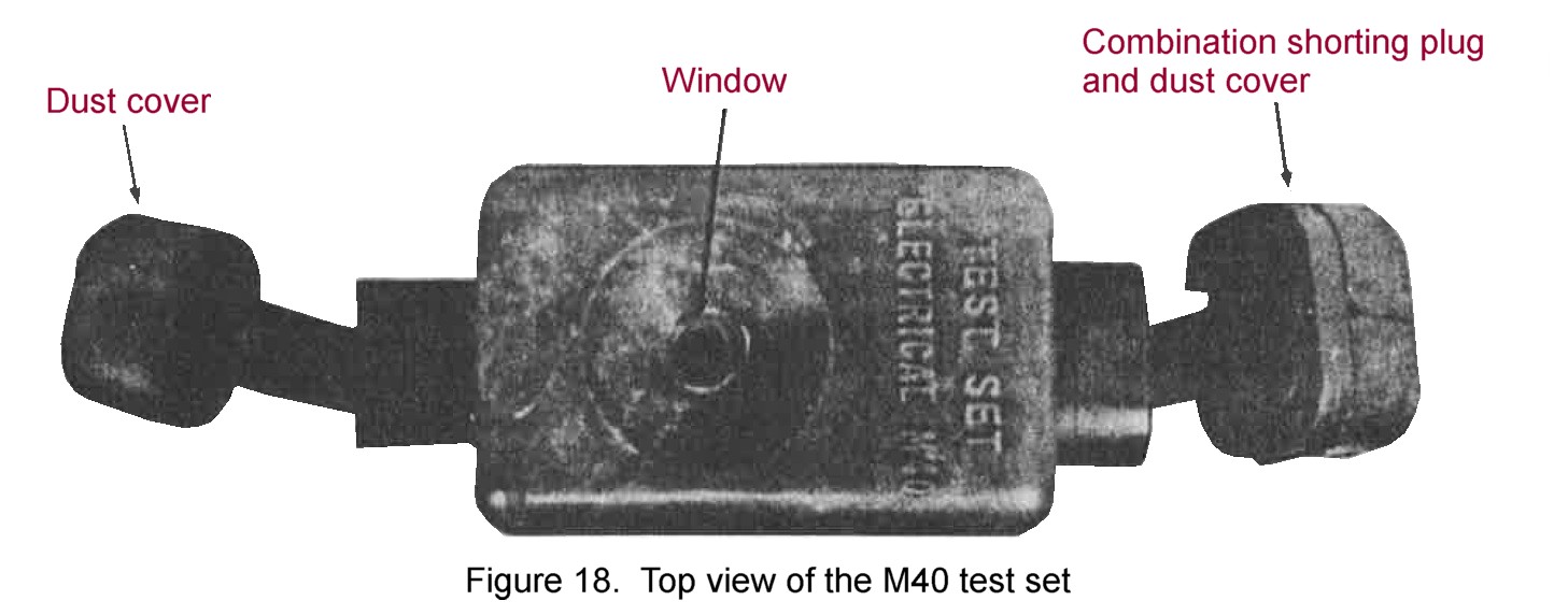
Figure 18. Top view of the M40 test set. |
position. Insure that no friendly personnel are near the blasting cap, as it may detonate.
DETAILED CIRCUIT TESTING IS CONDUCTED WITHOUT THE BLASTING CAP INSERTED INTO THE DETONATOR WELL.
(b) When the handle of the firing device is actuated, a lamp in the window of the test set will flash. This flash indicates ,that the blasting cap circuitry is satisfactory. If there is no flash, replace the blasting cap and retest.
(c) Immediately after the circuit test, the firing device is disconnected from the firing wire and the shorting plug dust cover is connected to the firing wire. The operator returns to the mine WITH THE FIRING DEVICE IN HIS POSSESSION and inserts the blasting cap into the detonator well. The operator then rechecks the aim of the mine and returns to his firing position.
(d) If an extended period of time lapses between the circuit test and the insertion of the blasting cap into the detonator well, or if the area is subjected to artillery or mortar fire, another test should be conducted.
Note. If time available precludes the conduct of a circuit test with the blasting cap removed from the mine, then an abbreviated test may be conducted with the blasting cap inserted into the detonator well. It an abbreviated test is conducted, all personnel must be under cover at least 250 meters away from the front and aides of the mine and 100 meters to the rear of the mine.
16. Disarming and destruction.
Disarming a Mine with an Electrical Firing System.
(1) Prior to disarming the mine, the firing device safety bail must be in the SAFE position.
(2) Disconnect the firing wire from the firing device. Replace the combination shorting plug dust cover on the firing wire connector and the dust cover on the firing device connector.
(3) Unscrew and remove the shipping plug priming-adapter containing the blasting cap from the mine. Remove the blasting cap and firing wire from the shipping plug priming-adapter. Reverse the shipping plug priming adapter, and screw the plug end of the adapter into the detonator well.
(4) Remove the firing wire from the stake. Reroll the blasting cap and firing wire and place it in its cardboard container.
(5) Remove the mine from its emplacement. Repack the mine and its accessories into their respective pockets in the bandoleer.
b. Disarming a Mine with a Nonelectrical Firing System.
(1) Prior to performing (2) through (6) below, render the firing device safe by replacing all safety pins.
(2) Disconnect the pull wire or tripwire from the nonelectric firing device.
(3) Remove the detonating cord and blasting cap from the detonator well.
(4) Using crimpers, cut the blasting cap free of the detonating cord. Nonelectric blasting caps and detonating cord crimped together can be separated only by cutting the blasting cap free of the detonating cord.
(5) Replace the shipping plug primingadapter and screw it into the detonator well, plug end down.
(6) Remove the mine from its emplaced position and repack. Store accessory items in appropriate containers.
c. Destruction of Mine to Prevent Enem11 Use. CLAYMORES can be most quickly destroyed by detonation or burning. For proper destruction procedures, see TM 9-1845-200.